EZ80L925048MOD Zilog, EZ80L925048MOD Datasheet - Page 19
EZ80L925048MOD
Manufacturer Part Number
EZ80L925048MOD
Description
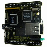
IC WEBSERVER 48MHZ 1MB MOD
Manufacturer
Zilog
Datasheet
1.EZ80L925048MOD.pdf
(38 pages)
Specifications of EZ80L925048MOD
Module/board Type
Development Module
For Use With/related Products
eZ80L92
Lead Free Status / RoHS Status
Lead free / RoHS Compliant
Other names
269-3166
EZ80L925048MOD
EZ80L925048MOD


PS017005-0903
Ethernet Connectors
GPIO Pins for Enabling LAN Activity, Sleep, Interrupt
An RJ45 loopback connector can be used to verify the correct operation of the
Receiver and the Transmitter. The green LED should be on if RX+ is connected
with TX+ and RX– is connected with TX–.
The eZ80L92 Module is equipped with an RJ45 connector that features integrated
magnetics (transformer, common mode chokes). The remaining pins on the
onboard RJ45 connector are not connected.
Node assignments for the RJ45 Ethernet connector are shown in Table 3.
Node assignment, in contrast to hub assignment, means that a straight-through
cable (equivalent pin numbers on both sides of the cable are connected to each
other) is used to attach the board to an Ethernet hub or switch. To connect the
eZ80L92 Module directly to another node (e.g., a personal computer), a crossover
cable must be used.
The EMAC can be additionally protected by placing a U9 ESD protection array on
the module. This array can be either of the LCDA15C-6 (Semtech) or ESDA25B1
(ST Microelectronics) devices.
GPIO input bit PD4 serves as an active High interrupt input for the EMAC’s
INTRQ0 output.
GPIO output bit PD7 can be used to enter the EMAC into SLEEP mode. When
pulling SLEEP (PD7) Low after enabling HWStandbyE and HWSleepE modes,
the chip draws lower current, because only the receiver is operating. A zero-Ohm
resistor at position R14 on the eZ80L92 Module is required for this function. In this
case, the PD6 pin is not available for GPIO on the I/O connector.
If LAN activity is detected, the LANACT signal is pulled Low. The LANACT is con-
nected to GPIO input PD6 and can be used in interrupt edge-detection mode to
wake up and reinitialize the Ethernet chip. A zero-Ohm resistor at position R15 on
Table 3. Ethernet Connector Pin Assignments
P R E L I M I N A R Y
Pin
1
2
3
6
Function
RX+
TX+
RX–
TX–
eZ80L92 Module Product Specification
Onboard Component Description
eZ80L925048MOD
13
Related parts for EZ80L925048MOD
Image
Part Number
Description
Manufacturer
Datasheet
Request
R

Part Number:
Description:
Communication Controllers, ZILOG INTELLIGENT PERIPHERAL CONTROLLER (ZIP)
Manufacturer:
Zilog, Inc.
Datasheet:

Part Number:
Description:
KIT DEV FOR Z8 ENCORE 16K TO 64K
Manufacturer:
Zilog
Datasheet:

Part Number:
Description:
KIT DEV Z8 ENCORE XP 28-PIN
Manufacturer:
Zilog
Datasheet:

Part Number:
Description:
DEV KIT FOR Z8 ENCORE 8K/4K
Manufacturer:
Zilog
Datasheet:

Part Number:
Description:
KIT DEV Z8 ENCORE XP 28-PIN
Manufacturer:
Zilog
Datasheet:

Part Number:
Description:
DEV KIT FOR Z8 ENCORE 4K TO 8K
Manufacturer:
Zilog
Datasheet:
Part Number:
Description:
CMOS Z8 microcontroller. ROM 16 Kbytes, RAM 256 bytes, speed 16 MHz, 32 lines I/O, 3.0V to 5.5V
Manufacturer:
Zilog, Inc.
Datasheet:
Part Number:
Description:
Low-cost microcontroller. 512 bytes ROM, 61 bytes RAM, 8 MHz
Manufacturer:
Zilog, Inc.
Datasheet:
Part Number:
Description:
Z8 4K OTP Microcontroller
Manufacturer:
Zilog, Inc.
Datasheet:
Part Number:
Description:
CMOS SUPER8 ROMLESS MCU
Manufacturer:
Zilog, Inc.
Datasheet:
Part Number:
Description:
SL1866 CMOSZ8 OTP Microcontroller
Manufacturer:
Zilog, Inc.
Datasheet:
Part Number:
Description:
SL1866 CMOSZ8 OTP Microcontroller
Manufacturer:
Zilog, Inc.
Datasheet:
Part Number:
Description:
OTP (KB) = 1, RAM = 125, Speed = 12, I/O = 14, 8-bit Timers = 2, Comm Interfaces Other Features = Por, LV Protect, Voltage = 4.5-5.5V
Manufacturer:
Zilog, Inc.
Datasheet:
Part Number:
Description:
Manufacturer:
Zilog, Inc.
Datasheet: