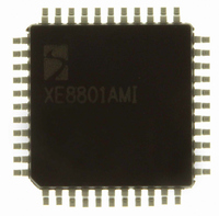
XE8801AMI027LF Semtech, XE8801AMI027LF Datasheet - Page 123

XE8801AMI027LF
Manufacturer Part Number
XE8801AMI027LF
Description
IC DAS 16BIT FLASH 8K MTP 44LQFP
Manufacturer
Semtech
Datasheet
1.XE8801AMI027LF.pdf
(135 pages)
Specifications of XE8801AMI027LF
Applications
Sensing Machine
Core Processor
RISC
Program Memory Type
FLASH (22 kB)
Controller Series
XE8000
Ram Size
512 x 8
Interface
UART, USRT
Number Of I /o
24
Voltage - Supply
2.4 V ~ 5.5 V
Operating Temperature
-40°C ~ 85°C
Mounting Type
Surface Mount
Package / Case
44-LQFP
For Use With
XE8000MP - PROG BOARD AND PROSTART2 CARD
Lead Free Status / RoHS Status
Lead free / RoHS Compliant
Available stocks
Company
Part Number
Manufacturer
Quantity
Price
Counters are enabled by CntAEnable, CntBEnable, CntCEnable, and CntDEnable in RegCntOn.
To stop the counter X, CntXEnable must be reset. To start the counter X, CntXEnable must be set. When
counters are cascaded, CntAEnable and CntCEnable also control respectively the counters B and D.
In the control registers, all registers must be written in this order: RegCntCtrlCk, RegCntConfig1, RegCntConfig2
and all RegCntX because several bits have no default values at reset.
All counters have a corresponding 8-bit read/write register: RegCntA, RegCntB, RegCntC, and RegCntD. When
read, these registers contain the counter value (or the captured counter value). When written, they modify the
counter comparison values.
For a correct acquisition of the counter value, use one of the three following methods:
When a value is written into the counter register while the counter is in counter mode, both the comparison value is
updated and the counter value is modified. In upcount mode, the register value is reset to zero. In downcount
mode, the comparison value is loaded into the counter. Due to the synchronization mechanism between the
processor clock domain and the external clock source domain, this modification of the counter value can be
postponed until the counter is enabled and it receives it’s first valid clock edge.
In the PWM mode, the counter value is not modified by the write operation in the counter register. Changing the
counter mode, does not update the counter value (no load in downcount mode).
The clock source for each counter can be individually selected by writing the appropriate value in the register
RegCntCtrlCk.
Table 18-10 gives the correspondence between the binary codes used for the configuration bits CntACkSel(1:0),
CntBCkSel(1:0), CntCCkSel(1:0) or CntDCkSel(1:0) and the clock source selected respectively for the counters
A, B, C or D.
© Semtech 2005
18.6 General counter registers operation
18.7 Clock selection
1) Stop the concerned counter, perform the read operation and restart the counter. While stopped, the
2) For slow operating counters (typically at least 8 times slower than the CPU clock), oversample the counter
3) Use the capture mechanism.
counter content is frozen and the counter does not take into account the clock edges delivered on the
external pin.
content and perform a majority operation on the consecutive read results to select the correct actual
content of the counter.
CntXCkSel(1:0)
11
10
01
00
Table 18-10: Clock sources for counters A, B, C and D
CounterA
PA(0)
CkRc/4
CkRc
CounterB
18-5
PA(1)
Clock source for
Ck128
CounterC
PA(2)
Ck32k
Ck1k
XE8801A – SX8801R
CounterD
PA(3)
www.semtech.com


