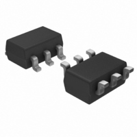
PIC10F200T-E/OT Microchip Technology, PIC10F200T-E/OT Datasheet - Page 8

PIC10F200T-E/OT
Manufacturer Part Number
PIC10F200T-E/OT
Description
IC PIC MCU FLASH 256X12 SOT23-6
Manufacturer
Microchip Technology
Series
PIC® 10Fr
Datasheets
1.PIC10F200T-IOT.pdf
(96 pages)
2.PIC10F200T-IOT.pdf
(6 pages)
3.PIC10F200T-IOT.pdf
(18 pages)
4.AC162052.pdf
(54 pages)
Specifications of PIC10F200T-E/OT
Core Size
8-Bit
Program Memory Size
384B (256 x 12)
Core Processor
PIC
Speed
4MHz
Peripherals
POR, WDT
Number Of I /o
3
Program Memory Type
FLASH
Ram Size
16 x 8
Voltage - Supply (vcc/vdd)
2 V ~ 5.5 V
Oscillator Type
Internal
Operating Temperature
-40°C ~ 125°C
Package / Case
SOT-23-6
Controller Family/series
PIC10
No. Of I/o's
4
Ram Memory Size
16Byte
Cpu Speed
4MHz
No. Of Timers
1
Digital Ic Case Style
SOT-23
Processor Series
PIC10F
Core
PIC
Data Bus Width
8 bit
Data Ram Size
16 B
Interface Type
USB
Maximum Clock Frequency
4 MHz
Number Of Programmable I/os
4
Number Of Timers
1
Operating Supply Voltage
2 V to 5.5 V
Maximum Operating Temperature
+ 125 C
Mounting Style
SMD/SMT
3rd Party Development Tools
52715-96, 52716-328, 52717-734
Development Tools By Supplier
PG164130, DV164035, DV244005, DV164005, PG164120
Minimum Operating Temperature
- 40 C
Package
6SOT-23
Device Core
PIC
Family Name
PIC10
Maximum Speed
4 MHz
Lead Free Status / RoHS Status
Lead free / RoHS Compliant
For Use With
AC162059 - HEADER INTRFC MPLAB ICD2 8/14PINXLT06SOT - SOCKET TRAN ICE 6SOT W/CABLEAC164321 - MODULE SKT 6L PM3 SOT23AC164037 - MODULE SKT 6L PROMATE II SOT23
Eeprom Size
-
Data Converters
-
Connectivity
-
Lead Free Status / Rohs Status
Details
Other names
PIC10F200T-E/OT
PIC10F200T-E/OTTR
PIC10F200T-E/OTTR
Available stocks
Company
Part Number
Manufacturer
Quantity
Price
Required Headers
AC162050, AC162058
DS51292R-page 8
TABLE 1: REQUIRED HEADERS BY DEVICE (CON’T)
Header Identification
The header AC number is used for ordering the header. However, this number is not
on the header board, as the board is often used for multiple headers by inserting differ-
ent ICE/ICD devices. To identify these header boards, use the following information.
Header Setup and Operation
For these headers, device peripherals need to be selected by setting jumper J1 to the
appropriate position. For AC162050, this will have the effect of selecting the device.
AC162050 Limitation:
These headers cannot be programmed while the GP1/RA1 pin is high (VIH) due to an
–ICD debug silicon issue. There are two work arounds:
1. Move the circuitry that makes GP1/RA1 high to another I/O pin during
2. Manually make GP1/RA1 low during programming (for debuggers that can
PIC16F716
PIC16F785/HV785
PIC18F13K50
PIC18F14K50
PIC18LF13K50
PIC18LF14K50
Note 1:
AC162050
AC162058
programming.
supply power to the target):
a) Disconnect the header from the target circuit.
b) Select Debugger>Settings, Power tab, and check “Power target circuit from
c) Connect GP1 to V
d) Program the header by selecting Debugger>Program.
e) Disconnect GP1 from V
f)
g) Insert the header into the target board.
h) Code is now programmed into the device and ready to be debugged.
i)
AC162050
AC162058
Header
Header
2:
...” if it is not already checked.
If you were NOT using a debug tool to power your target board, select
Debugger>Settings, Power tab, and uncheck “Power target circuit from ...”.
Repeat the process to reprogram the device.
Device
These ICE/ICD devices have limitations. See header section for details.
V
DDCORE
Jumper J1
PIC12F675-ICD
PIC12F683-ICD
Max
2-3
1-2
1-2
ICE/ICD Device
SS
Count
Pin
18
20
20
20
on the header.
SS
A/D Disabled
A/D Enabled
A/D Enabled
on the header.
Header Part
AC162054
AC162060
AC244023
AC244024
Number
Function
02-01662
PIC16F716-ICD
PIC16F785-ICD
PIC18F14K50-ICE
PIC18LF14K50-ICE
ICE/ICD Device
Board Assembly Number
© 2009 Microchip Technology Inc.
Used
(1)
Device Selected
PIC12F629
PIC12F675
PIC12F683
V
2.75V
DD
5.5V
5.5V
5.5V
3.6V
Max
(2)


