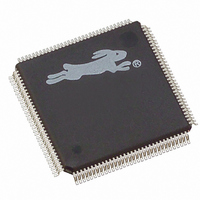
20-668-0011 Rabbit Semiconductor, 20-668-0011 Datasheet - Page 195

20-668-0011
Manufacturer Part Number
20-668-0011
Description
IC MPU RABIT3000A 55.5MHZ128LQFP
Manufacturer
Rabbit Semiconductor
Datasheet
1.20-668-0011.pdf
(312 pages)
Specifications of 20-668-0011
Processor Type
Rabbit 3000 8-Bit
Speed
55.5MHz
Voltage
2.5V, 2.7V, 3V, 3.3V
Mounting Type
Surface Mount
Package / Case
128-LQFP
Data Bus Width
8 bit
Maximum Clock Frequency
55.5 MHz
Operating Supply Voltage
1.8 V to 3.6 V
Maximum Operating Temperature
+ 85 C
Mounting Style
SMD/SMT
Minimum Operating Temperature
- 55 C
Number Of Programmable I/os
56
Lead Free Status / RoHS Status
Lead free / RoHS Compliant
Features
-
Lead Free Status / Rohs Status
Lead free / RoHS Compliant
Other names
316-1061
Available stocks
Company
Part Number
Manufacturer
Quantity
Price
Company:
Part Number:
20-668-0011
Manufacturer:
Rabbit Semiconductor
Quantity:
10 000
- Current page: 195 of 312
- Download datasheet (2Mb)
22. P
W
M
ULSE
IDTH
ODULATOR
22.1 Overview
The Pulse Width Modulator (PWM) consists of a 10-bit free running counter and four
width registers. A PWM output consists of a train of periodic pulses within a 1024-count
frame with a duty cycle that varies from 1/1024 to 1024/1024. Each PWM output is high
for n + 1 counts out of the 1024-clock count cycle, where n is the value held in the width
register. The PWM is clocked by the output of Timer A9 which is used to set the period.
Each PWM output high time can optionally be spread throughout the cycle to reduce rip-
ple on the externally filtered PWM output. The PWM outputs can be passed through a fil-
ter and used as a 10-bit D/A converter. The outputs can also be used to directly drive
devices such as motors or solenoids that have intrinsic filtering.
The PWM outputs can trigger a PWM interrupt on every PWM cycle, every other cycle,
every fourth cycle, or every eighth cycle. In addition, the PWM output can be suppressed
every other cycle, three out of every four cycles, or seven out of every eight cycles. These
options provide support for driving servos and to generate audio signals. The setup for this
interrupt is done in the PWL0R and PWL1R registers. The timing is shown below.
Chapter 22 Pulse Width Modulator
185
Related parts for 20-668-0011
Image
Part Number
Description
Manufacturer
Datasheet
Request
R

Part Number:
Description:
IC CPU RABBIT2000 30MHZ 100PQFP
Manufacturer:
Rabbit Semiconductor
Datasheet:

Part Number:
Description:
IC CPU RABBIT4000 128-LQFP
Manufacturer:
Rabbit Semiconductor
Datasheet:

Part Number:
Description:
Microprocessors - MPU Rabbit 3000 TFBGA Microprocessor
Manufacturer:
Rabbit Semiconductor

Part Number:
Description:
Microprocessors - MPU Rabbit 4000 LQFP Microprocessor
Manufacturer:
Rabbit Semiconductor

Part Number:
Description:
IC, I/O EXPANDER, 8BIT, 40MHZ, TQFP-64
Manufacturer:
Rabbit Semiconductor

Part Number:
Description:
SCRs 1.5A 200uA 400V Sensing
Manufacturer:
Littelfuse Inc
Datasheet:

Part Number:
Description:
CARD 6-RELAY SMARTSTAR SR9500
Manufacturer:
Rabbit Semiconductor
Datasheet:

Part Number:
Description:
WIRE-BOARD CONN RECEPTACLE, 6POS, 3.96MM
Manufacturer:
TE Connectivity
Datasheet:

Part Number:
Description:
ADAPTER 20 PIN .420" PLUGS(6PCS)
Manufacturer:
Logical Systems Inc.
Datasheet:

Part Number:
Description:
CONN BARRIER BLOCK .438" 20 POS
Manufacturer:
Cinch Connectors
Datasheet:

Part Number:
Description:
20 MODII 2PC HDR DR SHRD, ROHS
Manufacturer:
TE Connectivity
Datasheet:

Part Number:
Description:
WIRE-BOARD CONN RECEPTACLE, 6POS, 3.96MM
Manufacturer:
TE Connectivity
Datasheet:


