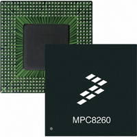
MPC8260AZUMHBB Freescale Semiconductor, MPC8260AZUMHBB Datasheet - Page 20

MPC8260AZUMHBB
Manufacturer Part Number
MPC8260AZUMHBB
Description
IC MPU POWERQUICC II 480-TBGA
Manufacturer
Freescale Semiconductor
Specifications of MPC8260AZUMHBB
Processor Type
MPC82xx PowerQUICC II 32-bit
Speed
266MHz
Voltage
2V
Mounting Type
Surface Mount
Package / Case
480-TBGA
Processor Series
MPC8xxx
Core
603e
Data Bus Width
32 bit
Maximum Clock Frequency
266 MHz
Maximum Operating Temperature
+ 105 C
Mounting Style
SMD/SMT
Minimum Operating Temperature
0 C
Leaded Process Compatible
Yes
Peak Reflow Compatible (260 C)
No
Rohs Compliant
No
For Use With
MPC8260ADS-TCOM - BOARD DEV ADS POWERQUICC II
Lead Free Status / RoHS Status
Contains lead / RoHS non-compliant
Features
-
Lead Free Status / Rohs Status
Lead free / RoHS Compliant
Available stocks
Company
Part Number
Manufacturer
Quantity
Price
Company:
Part Number:
MPC8260AZUMHBB
Manufacturer:
MOTOROLA
Quantity:
490
Company:
Part Number:
MPC8260AZUMHBB
Manufacturer:
Freescale Semiconductor
Quantity:
10 000
Part Number:
MPC8260AZUMHBB
Manufacturer:
FREE
Quantity:
20 000
Clock Configuration Modes
3
To configure the main PLL multiplication factor and the core, CPM, and 60x bus frequencies, the
MODCK[1–3] pins are sampled while HRESET is asserted.
modes. Another 49 modes are available by using the configuration pin (RSTCONF) and driving four pins
on the data bus.
3.1
Table 12
Table 13
Note also that basic modes are shown in boldface type.
20
MODCK_H–MODCK[1–3]
MODCK[1–3]
000
001
010
011
100
101
110
111
Clock Configuration Modes
0001_000
0001_001
0001_010
0001_011
0001_100
describes default clock modes for the MPC8260.
describes all possible clock configurations when using the hard reset configuration sequence.
MPC8260 PowerQUICC II Integrated Communications Processor Hardware Specifications, Rev. 2
Local Bus Mode
The UPM machine outputs change on the internal tick determined by the
memory controller programming; the AC specifications are relative to the
internal tick. Note that SDRAM and GPCM machine outputs change on
CLKin’s rising edge.
Clock configurations change only after POR is asserted.
Input Clock
Frequency
33 MHz
33 MHz
33 MHz
33 MHz
66 MHz
66 MHz
66 MHz
66 MHz
Frequency
Input Clock
33 MHz
33 MHz
33 MHz
33 MHz
33 MHz
CPM Multiplication
Table 13. Clock Configuration Modes
2,3,4
Table 12. Clock Default Modes
Factor
2.5
2.5
3
3
4
4
2
2
CPM Multiplication
Factor
2
2
2
2
2
NOTE
NOTE
2, 5
Frequency
100 MHz
100 MHz
133 MHz
133 MHz
133 MHz
133 MHz
166 MHz
166 MHz
CPM
Table 12
Frequency
66 MHz
66 MHz
66 MHz
66 MHz
66 MHz
CPM
Core Multiplication Factor Core Frequency
shows the eight basic configuration
1
2
Core Multiplication
2.5
2.5
4
5
4
5
3
3
Factor
4
5
6
7
8
Freescale Semiconductor
2, 6
133 MHz
166 MHz
133 MHz
166 MHz
166 MHz
200 MHz
166 MHz
200 MHz
Frequency
133 MHz
166 MHz
200 MHz
233 MHz
266 MHz
Core
2


