MC7447AHX1420LB Freescale Semiconductor, MC7447AHX1420LB Datasheet - Page 39
MC7447AHX1420LB
Manufacturer Part Number
MC7447AHX1420LB
Description
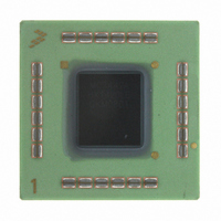
IC MPU RISC 1420MHZ 360-FCCBGA
Manufacturer
Freescale Semiconductor
Datasheet
1.MC7447AVS733NB.pdf
(56 pages)
Specifications of MC7447AHX1420LB
Processor Type
MPC74xx PowerPC 32-Bit
Speed
1.42GHz
Voltage
1.3V
Mounting Type
Surface Mount
Package / Case
360-FCCBGA
Lead Free Status / RoHS Status
Contains lead / RoHS non-compliant
Features
-
Available stocks
Company
Part Number
Manufacturer
Quantity
Price
Company:

Part Number:
MC7447AHX1420LB
Manufacturer:
Freescale Semiconductor
Quantity:
10 000


Table 15
and is relatively unaffected by bus voltage.
9.6
The MPC7447A requires high-resistive (weak: 4.7 KΩ) pull-up resistors on several control pins of the bus
interface to maintain the control signals in the negated state after they have been actively negated and
released by the MPC7447A or other bus masters. These pins are: TS, ARTRY, SHDO, and SHD1.
Some pins designated as being factory test pins must be pulled up to OV
proper device operation. The pins that must be pulled up to OV
pins that must be pulled down to GND are: L1_TSTCLK and TEST[4]. The CKSTP_IN signal should
likewise be pulled up through a pull-up resistor (weak or stronger: 4.7 KΩ–1 KΩ) to prevent erroneous
assertions of this signal.
In addition, the MPC7447A has one open-drain style output that requires a pull-up resistor (weak or
stronger: 4.7 KΩ–1 KΩ) if it is used by the system. This pin is CKSTP_OUT.
If pull-down resistors are used to configure BVSEL, the resistors should be less than 250 Ω (see
Because PLL_CFG[0:4] must remain stable during normal operation, strong pull-up and pull-down
resistors (1 KΩ or less) are recommended to configure these signals in order to protect against erroneous
switching due to ground bounce, power supply noise or noise coupling.
Freescale Semiconductor
summarizes the signal impedance results. The impedance increases with junction temperature
Pull-Up/Pull-Down Resistor Requirements
Z
0
Typical
Maximum
MPC7447A RISC Microprocessor Hardware Specifications, Rev. 5
Impedance
Figure 18. Driver Impedance Measurement
Data
Table 15. Impedance Characteristics
V
DD
= 1.5 V, OV
DD
= 1.8 V ± 5%, T
Pad
R
R
j
OV
OGND
N
P
= 5°–85°C
DD
DD
are: LSSD_MODE and TEST[0:3]; the
Processor Bus
SW2
SW1
33–42
31–51
DD
or down to GND to ensure
System Design Information
Unit
Table
Ω
Ω
12).
39
Related parts for MC7447AHX1420LB
Image
Part Number
Description
Manufacturer
Datasheet
Request
R

Part Number:
Description:
Manufacturer:
Freescale Semiconductor, Inc
Datasheet:
Part Number:
Description:
Manufacturer:
Freescale Semiconductor, Inc
Datasheet:
Part Number:
Description:
Manufacturer:
Freescale Semiconductor, Inc
Datasheet:
Part Number:
Description:
Manufacturer:
Freescale Semiconductor, Inc
Datasheet:
Part Number:
Description:
Manufacturer:
Freescale Semiconductor, Inc
Datasheet:
Part Number:
Description:
Manufacturer:
Freescale Semiconductor, Inc
Datasheet:
Part Number:
Description:
Manufacturer:
Freescale Semiconductor, Inc
Datasheet:
Part Number:
Description:
Manufacturer:
Freescale Semiconductor, Inc
Datasheet:
Part Number:
Description:
Manufacturer:
Freescale Semiconductor, Inc
Datasheet:
Part Number:
Description:
Manufacturer:
Freescale Semiconductor, Inc
Datasheet:
Part Number:
Description:
Manufacturer:
Freescale Semiconductor, Inc
Datasheet:
Part Number:
Description:
Manufacturer:
Freescale Semiconductor, Inc
Datasheet:
Part Number:
Description:
Manufacturer:
Freescale Semiconductor, Inc
Datasheet:
Part Number:
Description:
Manufacturer:
Freescale Semiconductor, Inc
Datasheet:
Part Number:
Description:
Manufacturer:
Freescale Semiconductor, Inc
Datasheet: