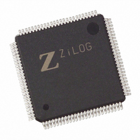
Z8018233ASC00TR Zilog, Z8018233ASC00TR Datasheet - Page 74

Z8018233ASC00TR
Manufacturer Part Number
Z8018233ASC00TR
Description
IC Z180 MPU 100LQFP
Manufacturer
Zilog
Datasheet
1.Z8018233FSG.pdf
(109 pages)
Specifications of Z8018233ASC00TR
Processor Type
Z180
Features
Smart Peripheral Controller
Speed
33MHz
Voltage
5V
Mounting Type
Surface Mount
Package / Case
100-LQFP
Lead Free Status / RoHS Status
Contains lead / RoHS non-compliant
Available stocks
Company
Part Number
Manufacturer
Quantity
Price
Zilog
3-74
16550 MIMIC REGISTERS (Continued)
Modem Status Register
Bit 7 Data Carrier Detect
This bit must be written by the Z180 MPU.
Bit 6 Ring Indicator
This bit must be written by the Z180 MPU.
Bit 5 Data Set Ready
This bit must be written by the Z180 MPU.
Bit 4 Clear to Send
This bit must be written by the Z180
Bit 3 Delta Data Carrier Detect
This bit is set to 1 whenever the Data Carrier Detect bit
changes state. This bit is reset when the PC/XT/AT reads
the Modem Status Register.
Bit 2 Trailing Edge Ring Indicator
This bit is set to 1 on the falling edge of the Ring Indicator
bit. This bit is reset when the PC/XT/AT reads the Modem
Status Register.
Bit 1 Delta Data Set Ready
This bit is set to 1 whenever the Data Set Ready bit
changes state. This bit is reset when the PC/XT/AT reads
the Modem Status Register.
Bit 0 Delta Clear To Send
This bit is set to 1 whenever the Clear To Send bit changes
state. This bit is reset when the PC/XT/AT reads the Modem
Status Register.
D7 D6 D5 D4 D3 D2 D1 D0
0
(Z180 MPU Read Only, Address xxF7H)
0
(PC Read/Write, Address 07H)
Figure 79. Scratch Register
0
0
0
0
0
0
™
MPU.
Divisor Latch (LS)
P R E L I M I N A R Y
PS009801-0301
Scratch Register
Bits 7-0 Scratch Register
This register is used by the PC/XT/AT programmer for
temporary data storage. The Z180 MPU is able to read this
register. If the PC/XT/AT writes to this register, no interrupt
to the Z180 MPU is generated.
Divisor Latch (LS)
Bit 7-0 Divisor Latch Most Significant Byte (MS)
This register contains the Low order byte of the Baud rate
divisor. Writing to this register with the PC/XT/AT will
generate an interrupt to the Z180 MPU. It can then read the
Baud rate divisor and set up the application.
Divisor Latch (MS)
Bit 7-0 Divisor Latch Most Significant Byte (MS)
This register contains the High order byte of the Baud rate
divisor. Writing to this register with the PC/XT/AT will
generate an interrupt to the Z180 MPU. It can then read the
Baud rate divisor and set up the application.
(PC Read/Write, Address 00H and DLAB=1)
(PC Read/Write, Address 01H and DLAB=1)
D7 D6 D5 D4 D3 D2 D1 D0
0
D7 D6 D5 D4 D3 D2 D1 D0
0
(Z180 MPU Read Only, Address xxF9H)
(Z180 MPU Read Only, Address xxF8H)
0
0
Figure 81. Divisor Latch (MS)
Figure 80. Divisor Latch (LS)
0
0
0
0
0
0
0
0
0
0
0
0
Z
ILOG
Divisor Latch (MS)
Scratch Register
I
NTELLIGENT
DS971820600
Z80182/Z8L182
P
ERIPHERAL


