MPC8540PX667LC Freescale Semiconductor, MPC8540PX667LC Datasheet - Page 16
MPC8540PX667LC
Manufacturer Part Number
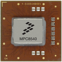
MPC8540PX667LC
Description
IC MPU 32BIT 667MHZ 783-FCPBGA
Manufacturer
Freescale Semiconductor
Specifications of MPC8540PX667LC
Processor Type
MPC85xx PowerQUICC III 32-Bit
Speed
667MHz
Voltage
1.2V
Mounting Type
Surface Mount
Package / Case
783-FCPBGA
For Use With
MPC8548CDS - DEV TOOLS CDS FOR 8548MPC8540ADS-BGA - BOARD APPLICATION DEV 8540CWH-PPC-8540N-VE - KIT EVAL SYSTEM MPC8540
Lead Free Status / RoHS Status
Lead free / RoHS Compliant
Features
-
Available stocks
Company
Part Number
Manufacturer
Quantity
Price
Company:

Part Number:
MPC8540PX667LC
Manufacturer:
Freescale Semiconductor
Quantity:
10 000


MPC8540 Architecture Overview
is 8 Gbps. Receive and transmit ports operate independently, resulting in an aggregate theoretical bandwidth of 16
Gbps.
3.15 RapidIO Message Unit
The MPC8540’s RapidIO messaging supports one inbox/outbox structure for data and one doorbell structure for
messages. Both chaining and direct modes are provided for the outbox, and messages can hold up to 16 packets of
256 bytes, or a total of 4 Kbytes.
3.16 Power Management
In addition to low-voltage operation and dynamic power management in its execution units, the MPC8540 supports
four power consumption modes: full-on, doze, nap, and sleep. The three low-power modes: doze, nap, and sleep,
can be entered under software control in the e500 core or by external masters accessing a configuration register.
Doze mode suspends execution of instructions in the e500 core. The core is left in a standby mode in which cache
snooping and time base interrupts are still enabled. Device logic external to the processor core is fully functional in
this mode.
Nap mode shuts down clocks to all the e500 functional units except the time base, which can be disabled separately.
No snooping is performed in nap mode, but the device logic external to the processor core is fully functional.
Sleep mode shuts down not only the e500 core, but all of the MPC8540 I/O interfaces as well. Only the interrupt
controller and power management logic remain enabled so that the device can be awakened.
3.17 Clocking
The MPC8540 takes in the PCI_CLK/SYSCLK signal as an input to the device PLL and multiplies it by an integer
from 1 to 16 to generate the core complex bus clock (the platform clock), which operates at the same frequency as
the DDR DRAM data rate (for example, 266 or 333 MHz). The L2 cache also operates at this frequency. The e500
core uses the CCB clock as an input to its PLL, which multiplies it again by 2, 2.5, 3, or 3.5 to generate the core
clock.
DLLs are used in the DDR SDRAM controller and the local bus memory controller (LBC) to generate memory
clocks. Six differential clock pairs are generated for DDR SDRAMs. Two clock outputs are generated for the LBC.
The RapidIO transmit clock may be sourced from one of three locations: the platform clock, the RapidIO receive
clock, or a special differential clock input. This input is designed to receive inputs from an external clock synthesis
device driving a clock with a frequency of up to 500 MHz.
3.18 Address Map
The MPC8540 supports a flexible physical address map. Conceptually, the address map consists of local space and
external address space. The local address map is 4 Gbytes. The MPC8540 can be made part of a larger system
address space through the mapping of translation windows. This functionality is included in the address translation
and mapping units (ATMUs). Both inbound and outbound translation windows are provided. The ATMUs allows
the MPC8540 to be part of larger address maps such as the PCI 64-bit address environment and the RapidIO
environment.
MPC8540 PowerQUICC III™ Integrated Host Processor Product Brief, Rev. 0.1
16
Freescale Semiconductor
Related parts for MPC8540PX667LC
Image
Part Number
Description
Manufacturer
Datasheet
Request
R

Part Number:
Description:
Manufacturer:
Freescale Semiconductor, Inc
Datasheet:
Part Number:
Description:
Manufacturer:
Freescale Semiconductor, Inc
Datasheet:
Part Number:
Description:
Manufacturer:
Freescale Semiconductor, Inc
Datasheet:
Part Number:
Description:
Manufacturer:
Freescale Semiconductor, Inc
Datasheet:
Part Number:
Description:
Manufacturer:
Freescale Semiconductor, Inc
Datasheet:
Part Number:
Description:
Manufacturer:
Freescale Semiconductor, Inc
Datasheet:
Part Number:
Description:
Manufacturer:
Freescale Semiconductor, Inc
Datasheet:
Part Number:
Description:
Manufacturer:
Freescale Semiconductor, Inc
Datasheet:
Part Number:
Description:
Manufacturer:
Freescale Semiconductor, Inc
Datasheet:
Part Number:
Description:
Manufacturer:
Freescale Semiconductor, Inc
Datasheet:
Part Number:
Description:
Manufacturer:
Freescale Semiconductor, Inc
Datasheet:
Part Number:
Description:
Manufacturer:
Freescale Semiconductor, Inc
Datasheet:
Part Number:
Description:
Manufacturer:
Freescale Semiconductor, Inc
Datasheet:
Part Number:
Description:
Manufacturer:
Freescale Semiconductor, Inc
Datasheet:
Part Number:
Description:
Manufacturer:
Freescale Semiconductor, Inc
Datasheet: