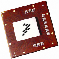
MPC8560PX833LC Freescale Semiconductor, MPC8560PX833LC Datasheet - Page 82

MPC8560PX833LC
Manufacturer Part Number
MPC8560PX833LC
Description
IC MPU PWRQUICC III 783-FCPBGA
Manufacturer
Freescale Semiconductor
Datasheet
1.MPC8560PX833LC.pdf
(104 pages)
Specifications of MPC8560PX833LC
Processor Type
MPC85xx PowerQUICC III 32-Bit
Speed
833MHz
Voltage
1.2V
Mounting Type
Surface Mount
Package / Case
783-FCPBGA
Family Name
MPC85XX
Device Core
PowerQUICC III
Device Core Size
32b
Frequency (max)
833MHz
Instruction Set Architecture
RISC
Supply Voltage 1 (typ)
1.2V
Operating Supply Voltage (max)
1.26V
Operating Supply Voltage (min)
1.14V
Operating Temp Range
0C to 105C
Operating Temperature Classification
Commercial
Mounting
Surface Mount
Pin Count
783
Package Type
FCBGA
For Use With
MPC8560ADS-BGA - BOARD APPLICATION DEV 8560
Lead Free Status / RoHS Status
Contains lead / RoHS non-compliant
Features
-
Lead Free Status / Rohs Status
Not Compliant
Available stocks
Company
Part Number
Manufacturer
Quantity
Price
Company:
Part Number:
MPC8560PX833LC
Manufacturer:
MOTOROLA
Quantity:
453
Company:
Part Number:
MPC8560PX833LC
Manufacturer:
Freescale Semiconductor
Quantity:
10 000
Part Number:
MPC8560PX833LC
Manufacturer:
FREESCALE
Quantity:
20 000
Thermal
16.2
This section provides thermal management information for the flip chip plastic ball grid array (FC-PBGA)
package for air-cooled applications. Proper thermal control design is primarily dependent on the
system-level design—the heat sink, airflow, and thermal interface material. The recommended attachment
method to the heat sink is illustrated in
board with the spring force centered over the die. This spring force should not exceed 10 pounds force.
The system board designer can choose between several types of heat sinks to place on the device. There
are several commercially-available heat sinks from the following vendors:
82
Junction-to-case thermal
Notes
1. Junction temperature is a function of die size, on-chip power dissipation, package thermal resistance, mounting site
2. Per JEDEC JESD51-6 with the board horizontal.
3. Thermal resistance between the die and the printed-circuit board per JEDEC JESD51-8. Board temperature is
4. Thermal resistance between the die and the case top surface as measured by the cold plate method (MIL SPEC-883
(board) temperature, ambient temperature, air flow, power dissipation of other components on the board, and board
thermal resistance
measured on the top surface of the board near the package.
Method 1012.1). Cold plate temperature is used for case temperature; measured value includes the thermal
resistance of the interface layer.
Aavid Thermalloy
80 Commercial St.
Concord, NH 03301
Internet: www.aavidthermalloy.com
Thermal Management Information
Figure 51. Package Exploded Cross-Sectional View with Several Heat Sink Options
Thermal Interface Material
MPC8560 Integrated Processor Hardware Specifications, Rev. 5
Table 60. Package Thermal Characteristics (continued)
Characteristic
Adhesive or
Heat Sink
Heat Sink
Figure
Lid
Clip
Die
51. The heat sink should be attached to the printed-circuit
Printed-Circuit Board
FC-PBGA Package
603-224-9988
Symbol
R
θJC
Value
0.8
Freescale Semiconductor
•C/W
Unit
C/W
Notes
4


