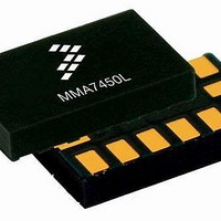
MMA7456LT Freescale Semiconductor, MMA7456LT Datasheet - Page 4

MMA7456LT
Manufacturer Part Number
MMA7456LT
Description
Board Mount Accelerometers 3-AXIS DIGTL 12C&SP1
Manufacturer
Freescale Semiconductor
Series
-r
Datasheet
1.MMA7456LR1.pdf
(35 pages)
Specifications of MMA7456LT
Sensing Axis
X, Y, Z
Acceleration
2 g, 4 g, 8 g
Sensitivity
64 count/g, 32 count/g, 16 count/g
Package / Case
LGA-14
Output Type
Digital
Supply Voltage (max)
3.6 V
Supply Voltage (min)
2.4 V
Supply Current
400 uA
Maximum Operating Temperature
+ 85 C
Minimum Operating Temperature
- 40 C
Axis
X, Y, Z
Acceleration Range
± 2g, 4g, 8g
Voltage - Supply
2.4 V ~ 3.6 V
Bandwidth
6kHz - XY, 3.4kHz - Z
Interface
I²C, SPI
Mounting Type
Surface Mount
Lead Free Status / Rohs Status
Lead free / RoHS Compliant
Available stocks
Company
Part Number
Manufacturer
Quantity
Price
Part Number:
MMA7456LT
Manufacturer:
FREESCALE
Quantity:
20 000
List of Tables
Pin Descriptions ............................................................................................................................................................................5
Maximum Ratings .........................................................................................................................................................................6
Operating Characteristics .............................................................................................................................................................7
Function Parameters for Detection ...............................................................................................................................................8
$16: Mode Control Register (Read/Write) ....................................................................................................................................9
Configuring the g-Select for 8-bit output using Register $16 with GLVL[1:0] bits .........................................................................9
Configuring the Mode using Register $16 with MODE[1:0] bits ...................................................................................................9
THOPT = 0 Absolute; THOPT = 1 Positive Negative .................................................................................................................10
$1B: Pulse Detection Threshold Limit Value (Read/Write) .........................................................................................................12
$1C: Pulse Duration Value (Read/Write) ....................................................................................................................................12
$1B: Pulse Detection Threshold Limit Value (Read/Write) .........................................................................................................13
$1D: Latency Time Value (Read/Write) ......................................................................................................................................13
$1B: Pulse Detection Threshold Limit Value (Read/Write) .........................................................................................................14
$1C: Pulse Duration Value (Read/Write) ....................................................................................................................................14
$1D: Latency Time Value (Read/Write) ......................................................................................................................................14
$1E: Time Window for 2nd Pulse Value (Read/Write) ................................................................................................................14
$18 Control 1 Register ................................................................................................................................................................15
Configuring the Interrupt settings using Register $18 with INTREG[1:0] bits .............................................................................15
$17: Interrupt Latch Reset (Read/Write) .....................................................................................................................................15
$0A: Detection Source Register (Read only) ..............................................................................................................................16
Pin Descriptions ..........................................................................................................................................................................19
User Register Summary .............................................................................................................................................................21
$00: 10bits Output Value X LSB (Read only) .............................................................................................................................21
$01: 10bits Output Value X MSB (Read only) ............................................................................................................................22
$02: 10bits Output Value Y LSB (Read only) .............................................................................................................................22
$03: 10bits Output Value Y MSB (Read only) ............................................................................................................................22
$05: 10bits Output Value X MSB (Read only) ............................................................................................................................22
$06: 8bits Output Value X (Read only) .......................................................................................................................................22
$07: 8bits Output Value Y (Read only) .......................................................................................................................................22
$08: 8bits Output Value Z (Read only) .......................................................................................................................................23
$09: Status Register (Read only) ...............................................................................................................................................23
$0A: Detection Source Register (Read only) ..............................................................................................................................23
$0D: I2C Device Address (Bit 6-0: Read only, Bit 7: Read/Write) ..............................................................................................23
$0E: User Information (Read Only: Optional) .............................................................................................................................23
$0F: “Who Am I” Value (Read only: Optional) ............................................................................................................................24
$10: Offset Drift X LSB (Read/Write) ..........................................................................................................................................24
$11: Offset Drift X MSB (Read/Write) .........................................................................................................................................24
$12: Offset Drift Y LSB (Read/Write) ..........................................................................................................................................24
$13: Offset Drift Y MSB (Read/Write) .........................................................................................................................................24
$14: Offset Drift Z LSB (Read/Write) ..........................................................................................................................................24
$15: Offset Drift Z MSB (Read/Write) .........................................................................................................................................25
$16: Mode Control Register (Read/Write) ..................................................................................................................................25
Configuring the g-Select for 8-bit output using Register $16 with GLVL[1:0] bits .......................................................................25
Configuring the Mode using Register $16 with MODE[1:0] bits .................................................................................................25
$17: Interrupt Latch Reset (Read/Write) .....................................................................................................................................26
$18 Control 1 (Read/Write) .........................................................................................................................................................26
Configuring the Interrupt settings using Register $18 with INTREG[1:0] bits .............................................................................26
$1A: Level Detection Threshold Limit Value (Read/Write) .........................................................................................................27
$1B: Pulse Detection Threshold Limit Value (Read/Write) .........................................................................................................27
$1C: Pulse Duration Value (Read/Write) ....................................................................................................................................27
$1D: Latency Time Value (Read/Write) ......................................................................................................................................27
$1E: Time Window for 2nd Pulse Value (Read/Write) ................................................................................................................27
Acceleration vs. Output (8-bit data) ............................................................................................................................................28
Sensors
Freescale Semiconductor
MMA7456L
4


