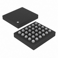
MAX9867EWV+T Maxim Integrated Products, MAX9867EWV+T Datasheet - Page 23

MAX9867EWV+T
Manufacturer Part Number
MAX9867EWV+T
Description
IC STEREO AUD CODEC LP 30WLP
Manufacturer
Maxim Integrated Products
Type
Stereo Audior
Datasheet
1.MAX9867EWVT.pdf
(55 pages)
Specifications of MAX9867EWV+T
Data Interface
I²C, Serial
Resolution (bits)
18 b
Number Of Adcs / Dacs
2 / 2
Sigma Delta
Yes
Dynamic Range, Adcs / Dacs (db) Typ
85 / 90
Voltage - Supply, Analog
1.65 V ~ 1.95 V
Voltage - Supply, Digital
1.65 V ~ 1.95 V
Operating Temperature
-40°C ~ 85°C
Mounting Type
Surface Mount
Package / Case
30-WLP
Lead Free Status / RoHS Status
Lead free / RoHS Compliant
Other names
MAX9867EWV+T
MAX9867EWV+TTR
MAX9867EWV+TTR
Status registers 0x00 and 0x01 are read-only registers
that report the status of various device functions. The
status register bits are cleared upon reading the status
Table 2. Status Registers
Status (Read Only)
Jack S ense ( Read O nl y)
AUX High (Read Only)
AUX Low (Read Only)
REGISTER
JKSNS
JKMIC
LSNS
JDET
BITS
CLD
SLD
ULK
AUX
______________________________________________________________________________________
Clip Detect Flag
Indicates that a signal has reached or exceeded full scale in the ADC or DAC.
Slew Level Detect Flag
When volume or gain changes are made, the slewing circuitry smoothly steps through all intermediate
settings. When SLD is set high, all slewing has completed and the volume or gain is at its final value. SLD
is also set when soft-start or stop is complete.
Digital PLL Unlock Flag
Indicates that the digital audio PLL has become unlocked and digital signal data is not reliable.
Headset Configuration Change Flag
JDET is set whenever there is a change in register 0x01, indicating that the headset configuration has
changed.
LOUTP State (Valid if SHDN = 0, JDETEN = 1)
LSNS is set when the voltage at LOUTP exceeds AVDD - 0.4V. An internal pullup from AVDD to LOUTP
causes this condition whenever there is no load on LOUTP. LSNS is only valid in differential and
capacitorless output modes.
JACKSNS State (Valid if JDETEN = 1)
JKSNS is set when the voltage at JACKSNS exceeds AVDD - 0.4V. An internal pullup from AVDD to
JACKSNS causes this condition whenever there is no load on JACKSNS.
Microphone Detection (Valid if PALEN or PAREN ≠ 00 and JDETEN = 1)
JKMIC is set when JACKSNS exceeds 0.95 x V
Auxiliary Input Measurement
AUX is a 16-bit signed two’s complement number representing the voltage measured at JACKSNS/AUX.
Before reading a value from AUX, set AUXCAP to 1 to ensure a stable reading. After reading the value,
set AUXCAP to 0.
Use the following formula to convert the AUX value into an equivalent JACKSNS/AUX voltage:
k = AUX value when AUXGAIN = 1. See the ADC section for complete details.
Voltage
LSNS
CLD
B7
Ultra-Low Power Stereo Audio Codec
=
0 738
.
JKSNS
SLD
B6
Device Status
V
×
⎛
⎝ ⎜
AUX
k
JKMIC
ULK
B5
⎞
⎠ ⎟
B4
0
0
AUX[15:8]
AUX[7:0]
register and are set the next time the event occurs.
Registers 0x02 and 0x03 report the DC level applied to
AUX. See the ADC section for more details and Table 2.
MICBIAS
FUNCTION
B3
0
0
.
B2
0
0
JDET
B1
0
B0
0
0
REGISTER
ADDRESS
0x00
0x01
0x02
0x03
23


