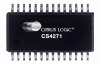
CS4271-DZZ Cirrus Logic Inc, CS4271-DZZ Datasheet - Page 3

CS4271-DZZ
Manufacturer Part Number
CS4271-DZZ
Description
IC CODEC 24BIT 114DB 28-TSSOP
Manufacturer
Cirrus Logic Inc
Type
Stereo Audior
Datasheet
1.CS4271-CZZ.pdf
(53 pages)
Specifications of CS4271-DZZ
Data Interface
Serial
Resolution (bits)
24 b
Number Of Adcs / Dacs
2 / 2
Sigma Delta
Yes
Dynamic Range, Adcs / Dacs (db) Typ
108 / 114
Voltage - Supply, Analog
4.75 V ~ 5.25 V
Voltage - Supply, Digital
3.1 V ~ 5.25 V
Operating Temperature
-40°C ~ 85°C
Mounting Type
Surface Mount
Package / Case
28-TSSOP
Audio Codec Type
Stereo
No. Of Adcs
2
No. Of Dacs
2
No. Of Input Channels
3
No. Of Output Channels
3
Adc / Dac Resolution
24bit
Sampling Rate
200kSPS
Ic Interface Type
I2C
Lead Free Status / RoHS Status
Lead free / RoHS Compliant
For Use With
598-1003 - EVAL BOARD CS4271 STEREO CODEC
Lead Free Status / RoHS Status
Lead free / RoHS Compliant, Lead free / RoHS Compliant
Available stocks
Company
Part Number
Manufacturer
Quantity
Price
Company:
Part Number:
CS4271-DZZ
Manufacturer:
CIRRUS
Quantity:
120
Company:
Part Number:
CS4271-DZZ
Manufacturer:
RFMD
Quantity:
2 500
TABLE OF CONTENTS
DS592F1
1. PIN DESCRIPTIONS - SOFTWARE MODE ............................................................................. 5
2. PIN DESCRIPTIONS - STAND-ALONE MODE ....................................................................... 7
3. CHARACTERISTICS AND SPECIFICATIONS ........................................................................ 9
4. TYPICAL CONNECTION DIAGRAM ..................................................................................... 23
5. APPLICATIONS ..................................................................................................................... 24
6. CONTROL PORT INTERFACE .............................................................................................. 35
SPECIFIED OPERATING CONDITIONS ................................................................................. 9
ABSOLUTE MAXIMUM RATINGS ........................................................................................... 9
DAC ANALOG CHARACTERISTICS - COMMERCIAL GRADE............................................ 10
DAC ANALOG CHARACTERISTICS - AUTOMOTIVE GRADE ............................................ 11
DAC COMBINED INTERPOLATION & ON-CHIP ANALOG FILTER RESPONSE................ 12
ADC ANALOG CHARACTERISTICS - COMMERCIAL GRADE............................................ 14
ADC ANALOG CHARACTERISTICS - AUTOMOTIVE GRADE ............................................ 15
ADC DIGITAL FILTER CHARACTERISTICS......................................................................... 16
DC ELECTRICAL CHARACTERISTICS ................................................................................ 17
DIGITAL CHARACTERISTICS............................................................................................... 17
SWITCHING CHARACTERISTICS - SERIAL AUDIO PORT................................................. 18
SWITCHING CHARACTERISTICS - I²C MODE CONTROL PORT....................................... 21
SWITCHING CHARACTERISTICS - SPI CONTROL PORT ................................................. 22
5.1 Stand-Alone Mode ........................................................................................................... 24
5.2 Control Port Mode ........................................................................................................... 27
5.3 De-Emphasis Filter .......................................................................................................... 31
5.4 Analog Connections ........................................................................................................ 32
5.5 Mute Control .................................................................................................................... 34
5.6 Synchronization of Multiple Devices ................................................................................ 34
5.7 Grounding and Power Supply Decoupling ....................................................................... 34
5.1.1 Recommended Power-Up Sequence ................................................................. 24
5.1.2 Master/Slave Mode ............................................................................................. 24
5.1.3 System Clocking ................................................................................................. 24
5.1.4 16-Bit Auto-Dither ............................................................................................... 26
5.1.5 Auto-Mute ........................................................................................................... 26
5.1.6 High Pass Filter ................................................................................................... 26
5.1.7 Interpolation Filter .............................................................................................. 26
5.1.8 Mode Selection & De-Emphasis ......................................................................... 26
5.1.9 Serial Audio Interface Format Selection ............................................................. 26
5.2.1 Recommended Power-Up Sequence - Access to Control Port Mode ................ 27
5.2.2 Master / Slave Mode Selection ........................................................................... 27
5.2.3 System Clocking ................................................................................................. 27
5.2.4 Internal Digital Loopback .................................................................................... 30
5.2.5 Dither for 16-Bit Data .......................................................................................... 30
5.2.6 Auto-Mute ........................................................................................................... 30
5.2.7 High Pass Filter and DC Offset Calibration ......................................................... 30
5.2.8 Interpolation Filter .............................................................................................. 31
5.2.9 De-Emphasis ...................................................................................................... 31
5.2.10 Oversampling Modes ........................................................................................ 31
5.4.1 Input Connections ............................................................................................... 32
5.4.2 Output Connections ............................................................................................ 33
5.1.3.1 Crystal Applications (XTI/XTO) ........................................................... 24
5.1.3.2 Clock Ratio Selection .......................................................................... 25
5.2.3.1 Crystal Applications (XTI/XTO) ........................................................... 27
5.2.3.2 Clock Ratio Selection .......................................................................... 28
CS4271
3


