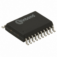
W6810ISG Nuvoton Technology Corporation of America, W6810ISG Datasheet - Page 4

W6810ISG
Manufacturer Part Number
W6810ISG
Description
IC VOICEBAND CODEC 5V 1CH 20SOP
Manufacturer
Nuvoton Technology Corporation of America
Type
PCMr
Specifications of W6810ISG
Data Interface
PCM Audio Interface
Resolution (bits)
8 b
Number Of Adcs / Dacs
1 / 1
Sigma Delta
No
Voltage - Supply, Analog
4.5 V ~ 5.5 V
Voltage - Supply, Digital
4.5 V ~ 5.5 V
Operating Temperature
-40°C ~ 85°C
Mounting Type
Surface Mount
Package / Case
20-SOP
Lead Free Status / RoHS Status
Lead free / RoHS Compliant
For Use With
W6810ES - EVALUATION SYSTEM FOR W6810W6810DK - KIT DEV/EVAL FOR W6810
Lead Free Status / RoHS Status
Compliant, Lead free / RoHS Compliant
Available stocks
Company
Part Number
Manufacturer
Quantity
Price
Part Number:
W6810ISG
Manufacturer:
NUVOTON
Quantity:
20 000
4. TABLE OF CONTENTS
1. GENERAL DESCRIPTION.................................................................................................................. 2
2. FEATURES ......................................................................................................................................... 2
3. BLOCK DIAGRAM .............................................................................................................................. 3
4. TABLE OF CONTENTS ...................................................................................................................... 4
5. PIN CONFIGURATION ....................................................................................................................... 6
6. PIN DESCRIPTION ............................................................................................................................. 7
7. FUNCTIONAL DESCRIPTION............................................................................................................ 8
8. TIMING DIAGRAMS.......................................................................................................................... 13
9. ABSOLUTE MAXIMUM RATINGS.................................................................................................... 20
10. ELECTRICAL CHARACTERISTICS ............................................................................................... 21
11. TYPICAL APPLICATION CIRCUIT ................................................................................................. 29
12. PACKAGE SPECICIFICATION....................................................................................................... 31
7.1. Transmit Path ................................................................................................................................ 8
7.2. Receive Path ................................................................................................................................. 9
7.3. Power Management..................................................................................................................... 10
7.4. PCM Interface .............................................................................................................................. 10
9.1. Absolute Maximum Ratings ......................................................................................................... 20
9.2. Operating Conditions ................................................................................................................... 20
10.1. General Parameters .................................................................................................................. 21
10.2. Analog Signal Level and Gain Parameters ...............................................................................22
10.3. Analog Distortion and Noise Parameters ..................................................................................23
10.4. Analog Input and Output Amplifier Parameters.........................................................................24
10.5. Digital I/O ................................................................................................................................... 26
7.3.1. Analog and Digital Supply ..................................................................................................... 10
7.3.2. Analog Ground Reference Bypass .......................................................................................10
7.3.3. Analog Ground Reference Voltage Outpt .............................................................................10
7.4.1. Long Frame Sync.................................................................................................................. 11
7.4.2. Short Frame Sync ................................................................................................................. 11
7.4.3. General Circuit Interface (GCI) ............................................................................................. 11
7.4.4. Interchip Digital Link (IDL)..................................................................................................... 12
7.4.5. System Timing ...................................................................................................................... 12
10.5.1. μ-Law Encode Decode Characteristics...............................................................................26
10.5.2. A-Law Encode Decode Characteristics ..............................................................................27
10.5.3. PCM Codes for Zero and Full Scale ...................................................................................28
10.5.4. PCM Codes for 0dBm0 Output ...........................................................................................28
- 4 -
W6810


