DS21Q41BT Maxim Integrated Products, DS21Q41BT Datasheet - Page 32

DS21Q41BT
Manufacturer Part Number
DS21Q41BT
Description
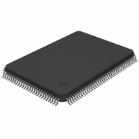
IC FRAMER T1 QUAD 128-TQFP
Manufacturer
Maxim Integrated Products
Datasheet
1.DS21Q41BT.pdf
(61 pages)
Specifications of DS21Q41BT
Controller Type
T1 Framer
Interface
Parallel/Serial
Voltage - Supply
4.5 V ~ 5.5 V
Current - Supply
30mA
Operating Temperature
0°C ~ 70°C
Mounting Type
Surface Mount
Package / Case
128-TQFP, 128-VQFP
Lead Free Status / RoHS Status
Contains lead / RoHS non-compliant
Available stocks
Company
Part Number
Manufacturer
Quantity
Price
Company:
Part Number:
DS21Q41BT
Manufacturer:
DS
Quantity:
3 279
Part Number:
DS21Q41BT
Manufacturer:
MAXIM/美信
Quantity:
20 000
Company:
Part Number:
DS21Q41BTN
Manufacturer:
DALLAS
Quantity:
104
MOSCR1:
MULTIFRAMES OUT OF SYNC COUNT REGISTER 1 (Address=25 Hex)
MOSCR2:
MULTIFRAMES OUT OF SYNC COUNT REGISTER 2 (Address=27 Hex)
NOTES:
1. The lower nibble of the counter at address 25 is used by the Path Code Violation Count Register.
2. MOSCR counts either errors in framing bit position (RCR2.0=0) or the number of multiframes out of
MULTIFRAMES OUT OF SYNC COUNTING ARRANGEMENTS Table 5-3
6.0 FDL/Fs EXTRACTION AND INSERTION
The DS21Q41B has the ability to extract/insert data from/into the Facility Data Link (FDL) in the ESF
framing mode and from/into Fs bit position in the D4 framing mode. Since SLC-96 utilizes the Fs bit
position, this capability can also be used in SLC-96 applications. The operation of the receive and
transmit sections will be discussed separately. Contact the factory for a copy of C language source code
for implementing the FDL on the DS21Q41B.
6.1 Receive Section
In the receive section, the recovered FDL bits or Fs bits are shifted bit-by-bit into the Receive FDL
register (RFDL). Since the RFDL is 8 bits in length, it will fill up every 2 ms (8 times 250 s). The
DS21Q41B will signal an external microcontroller that the buffer has filled via the SR2.4 bit. If enabled
via IMR2.4, the
user has 2 ms to read this data before it is lost. If the byte in the RFDL matches either of the bytes
programmed into the RFDLM1 or RFDLM2 registers, then the SR2.2 bit will be set to a 1 and the
pin will toggled low if enabled via IMR2.2. This feature allows an external microcontroller to ignore the
FDL or Fs pattern until an important event occurs.
(MSB)
MOS/FB11
MOS/FB7
FRAMING MODE
sync (RCR2.0=1).
(CCR2.3)
MOS/FB11
SYMBOL
MOS/FB0
ESF
ESF
D4
D4
MOS/FB10
MOS/FB6
INT
pin will toggle low indicating that the buffer has filled and needs to be read. The
POSITION
MOSCR1.7
MOSCR2.0
MOS/FB9
MOS/FB5
COUNT MOS OR F-BIT
ERRORS? (RCR2.0)
MOS/FB8
MOS/FB4
F-BIT
F-BIT
MOS
MOS
NAME AND DESCRIPTION
MSB of the 12-Bit multiframes out of sync or F-bit error count
(note 2)
LSB of the 12-bit multiframes out of sync or F-bit error count
(note 2)
32 of 61
MOS/FB3
(note 1)
number of multiframes out of sync
errors in the Ft pattern
number of multiframes out of sync
errors in the FPS pattern
WHAT IS COUNTED IN THE MOSCRs
MOS/FB2
(note 1)
MOS/FB1
(note 1)
MOS/FB0
(note 1)
(LSB)
MOSCR1
MOSCR2
DS21Q41B
INT


