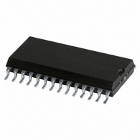
SJA1000T/N,112 NXP Semiconductors, SJA1000T/N,112 Datasheet - Page 44

SJA1000T/N,112
Manufacturer Part Number
SJA1000T/N,112
Description
IC STAND-ALONE CAN CTRLR 28-SOIC
Manufacturer
NXP Semiconductors
Datasheet
1.SJA1000TN1112.pdf
(68 pages)
Specifications of SJA1000T/N,112
Controller Type
CAN Interface
Interface
CAN
Voltage - Supply
4.5 V ~ 5.5 V
Current - Supply
15mA
Operating Temperature
-40°C ~ 125°C
Mounting Type
Surface Mount
Package / Case
28-SOIC (7.5mm Width)
Lead Free Status / RoHS Status
Lead free / RoHS Compliant
Other names
935277294112
SJA1000T/N
SJA1000T/N
SJA1000T/N
SJA1000T/N
Philips Semiconductors
Table 41 RX identifier 4 (EFF); can address 20; note 1
Notes
1. ID.X means identifier bit X.
2. Remote transmission request.
Remark: the received data length code located in the
frame information byte represents the real sent data length
code, which may be greater than 8 (depends on sender).
Nevertheless the maximum number of received data bytes
is 8. This should be taken into account by reading a
message from the receive buffer.
As described in Fig.8 the RXFIFO has space for
64 message bytes in total. It depends on the data length
how many messages can fit in it at one time. If there is not
enough space for a new message within the RXFIFO, the
CAN controller generates a data overrun condition the
moment this message becomes valid and the acceptance
test was positive. A message which is partly written into
the RXFIFO, when the data overrun situation occurs, is
deleted. This situation is indicated to the CPU via the
status register and the data overrun interrupt, if enabled.
6.4.15
With the help of the acceptance filter the CAN controller is
able to allow passing of received messages to the RXFIFO
only when the identifier bits of the received message are
equal to the predefined ones within the acceptance filter
registers.
The acceptance filter is defined by the Acceptance Code
Registers (ACRn) and the Acceptance Mask Registers
(AMRn). The bit patterns of messages to be received are
defined within the acceptance code registers.
The corresponding acceptance mask registers allow to
define certain bit positions to be ‘don’t care’.
Two different filter modes are selectable within the mode
register (MOD.3, AFM; see Section 6.4.3):
2000 Jan 04
Single filter mode (bit AFM is logic 1)
Dual filter mode (bit AFM is logic 0).
Stand-alone CAN controller
BIT 7
ID.4
A
CCEPTANCE FILTER
BIT 6
ID.3
BIT 5
ID.2
BIT 4
ID.1
44
6.4.15.1
In this filter configuration one long filter (4-bytes) could be
defined. The bit correspondences between the filter bytes
and the message bytes depend on the currently received
frame format.
Standard frame: if a standard frame format message is
received, the complete identifier including the RTR bit and
the first two data bytes are used for acceptance filtering.
Messages may also be accepted if there are no data bytes
existing due to a set RTR bit or if there is none or only one
data byte because of the corresponding data length code.
For a successful reception of a message, all single bit
comparisons have to signal acceptance.
Note, that the 4 least significant bits of AMR1 and ACR1
are not used. In order to be compatible with future products
these bits should be programmed to be ‘don’t care’ by
setting AMR1.3, AMR1.2, AMR1.1 and AMR1.0 to logic 1.
BIT 3
ID.0
Single filter configuration
RTR
BIT 2
(2)
BIT 1
0
Product specification
SJA1000
BIT 0
0


