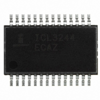
ICL3244ECAZ-T Intersil, ICL3244ECAZ-T Datasheet - Page 12

ICL3244ECAZ-T
Manufacturer Part Number
ICL3244ECAZ-T
Description
TRANSMITTER/RCVR RS232 28-SSOP
Manufacturer
Intersil
Type
Transceiverr
Datasheet
1.ICL3244ECAZ-T.pdf
(20 pages)
Specifications of ICL3244ECAZ-T
Number Of Drivers/receivers
3/5
Protocol
RS232
Voltage - Supply
3 V ~ 5.5 V
Mounting Type
Surface Mount
Package / Case
28-SSOP
Peak Reflow Compatible (260 C)
Yes
Rohs Compliant
Yes
Lead Free Status / RoHS Status
Lead free / RoHS Compliant
Other names
ICL3244ECAZ-TTR
Available stocks
Company
Part Number
Manufacturer
Quantity
Price
Company:
Part Number:
ICL3244ECAZ-T
Manufacturer:
INTERSIL
Quantity:
10 071
another computer via a detachable cable. Detaching the
cable allows the internal receiver pull-down resistors to pull
the inputs to GND (an invalid RS-232 level), causing the
30µs timer to time-out and drive the IC into powerdown.
Reconnecting the cable restores valid levels, causing the IC
to power back up.
Hybrid Automatic Powerdown Options
For devices which communicate only through a detachable
cable, connecting INVALID to FORCEOFF (with
FORCEON = 0) may be a desirable configuration. While the
cable is attached INVALID and FORCEOFF remain high, so
the enhanced automatic powerdown logic powers down the
RS-232 device whenever there is 30 seconds of inactivity on
the receiver and transmitter inputs. Detaching the cable
allows the receiver inputs to drop to an invalid level (GND),
so INVALID switches low and forces the RS-232 device to
power down. The ICL32XXE remains powered down until
the cable is reconnected (INVALID = FORCEOFF = 1) and a
transition occurs on a receiver or transmitter input (see
Figure 7). For immediate power up when the cable is
reattached, connect FORCEON to FORCEOFF through a
network similar to that shown in Figure 5.
TRANSMITTER
TRANSMITTER
RECEIVER
OUTPUTS
OUTPUT
OUTPUT
INVALID
INPUTS
INPUTS
READY
V
CC
V+
V-
0
t
INVL
FIGURE 8. ENHANCED AUTOMATIC POWERDOWN, INVALID AND READY TIMING DIAGRAMS
12
t
INVH
ICL3224E, ICL3226E, ICL3244E
t
AUTOPWDN
Ready Output (ICL3224E and ICL3226E only)
The Ready output indicates that the ICL322XE is ready to
transmit. Ready switches low whenever the device enters
powerdown, and switches back high during power-up when
V- reaches -4V or lower.
Capacitor Selection
The charge pumps require 0.1µF capacitors for 3.3V
operation. For other supply voltages refer to Table 3 for
capacitor values. Do not use values smaller than those listed
in Table 3. Increasing the capacitor values (by a factor of 2)
reduces ripple on the transmitter outputs and slightly
reduces power consumption. C
increased without increasing C
increase C
maintain the proper ratios (C
t
WU
FIGURE 9. CONNECTIONS FOR AUTOMATIC POWERDOWN
CPU
1
t
AUTOPWDN
without also increasing C
WHEN NO VALID RECEIVER SIGNALS ARE
PRESENT
UART
I/O
1
to the other capacitors).
1
2
’s value, however, do not
, C
3
, and C
t
WU
2
ICL32XXE
, C
3
, and C
4
can be
}
4
INVALID
REGION
to


