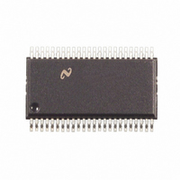
DS89C387TMEA/NOPB National Semiconductor, DS89C387TMEA/NOPB Datasheet - Page 6

DS89C387TMEA/NOPB
Manufacturer Part Number
DS89C387TMEA/NOPB
Description
IC LINE DRV CMOS DIF 12CH 48SSOP
Manufacturer
National Semiconductor
Type
Driverr
Datasheet
1.DS89C387TMEANOPB.pdf
(12 pages)
Specifications of DS89C387TMEA/NOPB
Number Of Drivers/receivers
12/0
Protocol
RS422
Voltage - Supply
4.5 V ~ 5.5 V
Mounting Type
Surface Mount
Package / Case
48-SSOP
Lead Free Status / RoHS Status
Lead free / RoHS Compliant
Other names
*DS89C387TMEA
*DS89C387TMEA/NOPB
DS89C387TMEA
*DS89C387TMEA/NOPB
DS89C387TMEA
Available stocks
Company
Part Number
Manufacturer
Quantity
Price
Company:
Part Number:
DS89C387TMEA/NOPB
Manufacturer:
TI
Quantity:
154
www.national.com
Typical Application
* R
Application Information
SKEW
Skew may be thought of in a lot of different ways, the next few
paragraphs should clarify what is represented by “Skew” in
the datasheet and how it is determined. Skew, as used in this
databook, is the absolute value of a mathematical difference
between two propagation delays. This is commonly accepted
throughout the semiconductor industry. However, there is no
standardized method of measuring propagation delay, from
which skew is calculated, of differential line drivers. Elucidat-
ing, the voltage level, at which propagation delays are mea-
sured, on both input and output waveforms are not always
In Figure 2, VX, where X is a number, is the waveform voltage
level at which the propagation delay measurement either
starts or stops. Furthermore, V1 and V2 are normally identi-
cal. The same is true for V3 and V4. However, as mentioned
before, these levels are not standardized and may vary, even
with similar devices from other companies. Also note, NC (no
connection) in Figure 1 means the pin is not used in propa-
gation delay measurement for the corresponding circuit.
The single-ended skew provides information about the pulse
width distortion of the output waveform. The lower the skew,
the less the output waveform will be distorted. For best case,
skew would be zero, and the output duty cycle would be 50%,
assuming the input has a 50% duty cycle.
T
is optional although highly recommended to reduce reflection.
Waveforms for Circuit 1
FIGURE 6. Circuits for Measuring Single-Ended Propagation Delays (See Figure 7)
FIGURE 7. Propagation Delay Waveforms for Circuit 1 and Circuit 2 (See Figure 6)
(Circuit 1)
1208609
FIGURE 5. Two-Wire Balanced System, RS-422
1208611
6
consistant. Therefore, skew calculated in this datasheet, may
not be calculated the same as skew defined in another. This
is important to remember whenever making a skew compar-
ison.
Skew may be calculated for the DS89C387, from many dif-
ferent propagation delay measurements. They may be clas-
sified into three categories, single-ended, differential, and
complementry. Single-ended skew is calculated from t
t
calculated from t
8, 9). Complementry skew is calculated from t
measurements (see Figures 10, 11).
FIGURE 8. Circuit for Measuring Differential Propagation
PLH
measurements (see Figures 6, 7). Differential skew is
PHLD
Waveforms for Circuit 2
Delays (See Figure 9)
and t
(Circuit 2)
(Circuit 3)
PLHD
measurements (see Figures
1208608
1208610
1208613
PHL
and t
PHL
1208612
and
PLH


