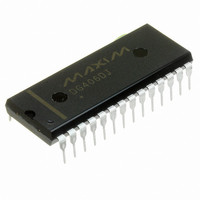
MAX214CPI+ Maxim Integrated Products, MAX214CPI+ Datasheet - Page 9

MAX214CPI+
Manufacturer Part Number
MAX214CPI+
Description
IC TXRX RS232 PROG DTE/DCE 28DIP
Manufacturer
Maxim Integrated Products
Type
Transceiverr
Datasheet
1.MAX214CWI.pdf
(12 pages)
Specifications of MAX214CPI+
Number Of Drivers/receivers
3/5
Protocol
RS232
Voltage - Supply
4.5 V ~ 5.5 V
Mounting Type
Through Hole
Package / Case
28-DIP (0.600", 15.24mm)
Propagation Delay Time Ns
100 ns
Operating Supply Voltage
4.5 V to 5.5 V
Supply Current
20 mA
Operating Temperature Range
0 C to + 70 C
Data Rate
116 Kbps
Mounting Style
SMD/SMT
Lead Free Status / RoHS Status
Lead free / RoHS Compliant
When using the minimum recommended capacitor
values, make sure the capacitance value does not
degrade excessively as the operating temperature
v a r i e s .
larger nominal value (for example, 2 times larger).
The effective series resistance (ESR) of the capaci-
t o r s m a y v a r y o v e r t e m p e r a t u r e a n d i n c r e a s e
when below 0°C. ESR influences the amount of rip-
ple on V+ and V-, so if low ripple is required over
wide temperature ranges, use larger capacitors or
low-ESR types.
To reduce the output impedance at V+ and V-, use
larger capacitors (up to 10µF). This can be useful
when “stealing” power from V+ or from V-.
Figure 3 shows the MAX214 driver outputs when exiting
shutdown. As they become active, the two driver out-
puts are shown going to opposite RS-232 levels (one
driver input is high, the other is low). Each driver is
loaded with 3kΩ in parallel with 2.5nF.
Decouple V
value as the charge-pump capacitors.
A small amount of power can be drawn from V+ and V-,
although this will reduce noise margins. See the
Output Voltage vs. Load Current graph in the Typical
Operating Characteristics . Increasing the charge-
Driver Outputs when Exiting Shutdown
I f i n d o u b t , u s e c a p a c i t o r s w i t h a
CC
to ground with a capacitor of the same
_______________________________________________________________________________________
V+ and V- as Power Supplies
Power-Supply Bypassing
Programmable DTE/DCE,
+5V RS-232 Transceiver
pump capacitor sizes up to 10µF reduces the imped-
ance of the V+ and V- outputs.
The MAX214 maintains the RS-232 ±5.0V minimum
driver output voltage even at high data rates. The
Typical Operating Characteristics show transmitter out-
put voltage levels driving 3kΩ in parallel with various
capacitive loads at data rates up to 120kbps.
Figure 3. Transmitter Outputs When Exiting Shutdown
+5V
0V
A = TRANSMITTER OUTPUT HIGH, +5V/div
B = TRANSMITTER OUTPUT LOW, +5V/div
C = SHDN INPUT, +5V/div
HORIZONTAL = 200 s
High Data Rates
C
B
+10V
A
+5V
0V
-5V
-10V
9


