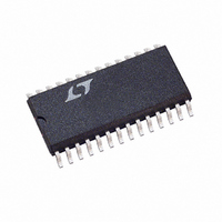
LTC1535CSW Linear Technology, LTC1535CSW Datasheet

LTC1535CSW
Specifications of LTC1535CSW
Available stocks
Related parts for LTC1535CSW
LTC1535CSW Summary of contents
Page 1
... A fail-safe feature defaults to a high output state when the receiver inputs are open or shorted. L, LT, LTC, LTM, Linear Technology and the Linear logo are registered trademarks of Linear Technology Corporation. All other trademarks are the property of their respective owners. ** ...
Page 2
... ORDER INFORMATION LEAD FREE FINISH TAPE AND REEL LTC1535CSW#PBF LTC1535CSW#TRPBF LTC1535ISW#PBF LTC1535ISW#TRPBF Consult LTC Marketing for parts specifi ed with wider operating temperature ranges. *The temperature grade is identifi label on the shipping container. For more information on lead free part marking, go to: For more information on tape and reel specifi ...
Page 3
ELECTRICAL CHARACTERISTICS temperature range, otherwise specifi cations are at T SYMBOL PARAMETER V V Supply Range Supply Range CC2 CC2 I V Supply Current Supply Current CC2 CC2 V Differential Driver Output ...
Page 4
LTC1535 ELECTRICAL CHARACTERISTICS temperature range, otherwise specifi cations are at T SYMBOL PARAMETER t Data Sample Jitter SJ f Max Baud Rate MAX t Driver Input to Output PLH t Driver Input to Output PHL Driver Rise ...
Page 5
TYPICAL PERFORMANCE CHARACTERISTICS V Supply Current CC vs Temperature 130 COOPER CC CTX02-14659 120 TRANSFORMER 110 R = 54Ω L 100 120Ω OPEN –50 –25 0 ...
Page 6
LTC1535 TYPICAL PERFORMANCE CHARACTERISTICS Receiver Output High Voltage vs Temperature 4 8mA 4 4.5V CC 3.5 3.0 –50 – 100 125 150 TEMPERATURE (°C) 1535 G10 Driver Output ...
Page 7
PIN FUNCTIONS POWER SIDE V (Pin 1): 5V Supply. Bypass to GND with 10μF CC capacitor. ST1 (Pin 2): DC Converter Output Transformer. ST2 (Pin 3): DC Converter Output Transformer. GND (Pin 4): Ground. ...
Page 8
LTC1535 TEST CIRCUIT 10μ MAX RO BAUD RATE GND 4 1 LOGIC COMMON 1 Figure 1. Self-Oscillation at Maximum Data Rate (Test ...
Page 9
SWITCHING TIME WAVEFORMS – OD2 A – B –V OD2 ...
Page 10
LTC1535 APPLICATIONS INFORMATION Isolation Barrier and Sampled Communication The LTC1535 uses the SW-28 isolated lead frame package to provide capacitive isolation barrier between the logic interface and the RS485 driver/receiver pair. The barrier provides 2500V of isolation. Communication between RMS ...
Page 11
APPLICATIONS INFORMATION Driver Output and Slow Slew Rate Control The LTC1535 uses a proprietary driver output stage that allows a common mode voltage range that extends beyond the power supplies. Thus, the high impedance state is maintained over the full ...
Page 12
LTC1535 APPLICATIONS INFORMATION Table 1. List of Transformers Designed for LTC1535 MANUFACTURER Cooper Cooper Epcos AG (Germany) (USA) Midcom Minntronix Pulse FEE (France) Sumida (Japan) Transpower Table 2. Fault Mode Behavior FUNCTION (PINS) DC/DC Converter ( ...
Page 13
APPLICATIONS INFORMATION High Voltage Considerations The LTC1535 eliminates ground loops on data commun- ication lines. However, such isolation can bring potentially dangerous voltages onto the circuit board. An example would be accidental faulting to 117V AC at some point on ...
Page 14
LTC1535 APPLICATIONS INFORMATION DI Y-Z Figure 13. Driver Propagation Delay with Sample Jitter. SLO = Figure 15. Driver Output. = 5V, SLO = 27Ω, V CC2 Y-Z Figure 17. Driver Differential Output. = 5V, ...
Page 15
TYPICAL APPLICATION RO RE LTC1535 DE DI (20a) Noninverting Figure 20. Confi guring Receiver for TTL Level Input. Y and Z Outputs Are TTL Compatible with No Modifi cation 2 ST1 10μ ...
Page 16
LTC1535 PACKAGE DESCRIPTION 28-Lead Plastic Small Outline Isolation Barrier (Wide .300 Inch) .291 – .299** (7.391 – 7.595) .010 – .029 45° (0.254 – 0.737) .009 – .013 (0.229 – 0.330) NOTE 2 .016 – .050 (0.406 – 1.270) NOTE: ...
Page 17
... Revise Figure 1. Update Tables 1 and 3 Information furnished by Linear Technology Corporation is believed to be accurate and reliable. However, no responsibility is assumed for its use. Linear Technology Corporation makes no representa- tion that the interconnection of its circuits as described herein will not infringe on existing patent rights. LTC1535 ...
Page 18
... TA05 2 COMMENTS ± 5% Accurate with No Optoisolator Required 10Mbps, Pin Compatible with LTC485 2.5V Isolated Reference, 3000V Isolation RMS ±15kV ESD Protection, Industry Standard Pinout ±15kV ESD Protection, Fail-Safe Receiver LT 1209 REV B • PRINTED IN USA © LINEAR TECHNOLOGY CORPORATION 2009 1535fb ...


