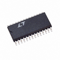
LTC1535CSW Linear Technology, LTC1535CSW Datasheet - Page 13

LTC1535CSW
Manufacturer Part Number
LTC1535CSW
Description
IC LINE TRANSCEIVER 28-SOIC
Manufacturer
Linear Technology
Type
Transceiverr
Datasheet
1.LTC1535CSW.pdf
(18 pages)
Specifications of LTC1535CSW
Number Of Drivers/receivers
1/1
Protocol
RS485
Voltage - Supply
4.5 V ~ 5.5 V
Mounting Type
Surface Mount
Package / Case
28-SOIC (7.5mm Width)
Lead Free Status / RoHS Status
Contains lead / RoHS non-compliant
Other names
Q1471168
Available stocks
Company
Part Number
Manufacturer
Quantity
Price
Company:
Part Number:
LTC1535CSW
Manufacturer:
LINEAR
Quantity:
2 945
Part Number:
LTC1535CSW
Manufacturer:
LT
Quantity:
20 000
Company:
Part Number:
LTC1535CSW#PBF
Manufacturer:
LT
Quantity:
6 592
Part Number:
LTC1535CSW#PBF
Manufacturer:
LINEAR/凌特
Quantity:
20 000
Company:
Part Number:
LTC1535CSW#TRPBF
Manufacturer:
EXAR
Quantity:
1 150
APPLICATIONS INFORMATION
High Voltage Considerations
The LTC1535 eliminates ground loops on data commun-
ication lines. However, such isolation can bring potentially
dangerous voltages onto the circuit board. An example
would be accidental faulting to 117V AC at some point
on the cable which is then conducted to the PC board.
Figure 12 shows how to detect and warn the user or
installer that a voltage fault condition exists on the twisted
pair or its shield. A small (3.2mm) glow lamp is connected
between GND2 (the isolated ground) and the equipment’s
safety “earth” ground. If a potential of more than 75V
AC is present on the twisted pair or shield, B1 will light,
indicating a wiring fault. Resistors R3 and R4 are used
to ballast the current in B1. Two resistors are necessary
because they can only stand off 200V each, as well as for
power dissipation. As shown, the circuit can withstand a
direct fault to a 440V 3-phase system.
Other problems introduced by fl oating the twisted pair
include the collection of static charge on the twisted pair,
its shield and the attached circuitry. Resistors R1 and R2
2
EQUIPMENT SAFETY GROUND
EARTH GROUND
FLOATING RS485 COMMON
Figure 12. Detecting Fault Conditions
LTC1535
GND2
2
2
R1*
470k
R2*
470k
A
Y
B
Z
C1***
10nF
provide a path to shunt static charge safely to ground.
Again, two resisitors are necessary to withstand high
voltage faults. Electrostatic spikes, electromagnetically
induced transients and radio frequency pickup are shunted
by addition capacitor C1.
Receiver Inputs Fail-Safe
The LTC1535 features an input common mode range
covering the entire RS485 specifi ed range of –7V to 12V.
Differential signals of greater than ± 200mV within the
specifi ed input common mode range will be converted
to TTL compatible signals at the receiver outputs, RO
and RO2. A small amount of input hyteresis is included
to minimize the effects of noise on the line signals. If
the receiver inputs are fl oating or shorted, a designed-in
receiver offset guarantees a fail-safe logic high at the
receiver outputs. If a fail-safe logic low is desired, connect
as shown in Figure 19.
*
** IRC WCR1210
*** PANASONIC ECQ-U2A103MV
2
IRC WCR1206
R3**
100k
R4**
100k
B1
CN2R (JKL)
TWISTED-PAIR
NETWORK
1535 F12
LTC1535
13
1535fb


