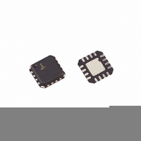
ISL4221EIRZ Intersil, ISL4221EIRZ Datasheet - Page 8

ISL4221EIRZ
Manufacturer Part Number
ISL4221EIRZ
Description
IC TXRX 1TX/1RX 3V RS-232 16-QFN
Manufacturer
Intersil
Type
Transceiverr
Datasheet
1.ISL3232EIRZ.pdf
(14 pages)
Specifications of ISL4221EIRZ
Number Of Drivers/receivers
2/2
Protocol
RS232
Voltage - Supply
2.7 V ~ 5.5 V
Mounting Type
Surface Mount
Package / Case
16-VQFN Exposed Pad, 16-HVQFN, 16-SQFN, 16-DHVQFN
Package
16QFN EP
Data Transmission Topology
Point-to-Point
Interface Standards
ElA/TIA-232|RS-232|V.24|V.28
Data Rate
0.5 Mbps
Function
Line Transmitter/Receiver
Number Of Transmitters
1
Transmitter Signal Type
Single-Ended
Transmitter Communication Type
RS-232
Driving Mode
3-State
Typical Single Supply Voltage
3.3|5 V
Lead Free Status / RoHS Status
Lead free / RoHS Compliant
Available stocks
Company
Part Number
Manufacturer
Quantity
Price
Company:
Part Number:
ISL4221EIRZ
Manufacturer:
Intersil
Quantity:
915
Company:
Part Number:
ISL4221EIRZ
Manufacturer:
Intersil
Quantity:
291
Low Power Operation
These 3V devices require a nominal supply current of
0.3mA, even at V
power-down mode). This is considerably less than the 5mA
to 11mA current required by comparable 5V RS-232 devices,
allowing users to reduce system power simply by switching to
this new family.
Power-down Functionality (Excluding
ISL3232E)
The already low current requirement drops significantly when
the device enters power-down mode. In power-down, supply
current drops to 150nA because the on-chip charge pump
turns off (V+ collapses to V
transmitter outputs three-state. Receiver outputs are
unaffected by power-down; refer to Table 2 for details. This
micro-power mode makes the ISL4221E, ISL4223E ideal for
battery-powered and portable applications.
Software Controlled (Manual) Power-down
The ISL4221E, ISL4223E family provides pins that allow the
user to force the IC into the low power, standby state.
The ISL4221E, ISL4223E utilize a two pin approach where
the FORCEON and FORCEOFF inputs determine the IC’s
mode. For always enabled operation, FORCEON and
FORCEOFF are both strapped high. To switch between active
and power-down modes, under logic or software control, only
the FORCEOFF input need be driven. The FORCEON state
isn’t critical, as FORCEOFF dominates over FORCEON.
Nevertheless, if strictly manual control over power-down is
desired, the user must strap FORCEON high to disable the
automatic power-down circuitry.
Connecting FORCEOFF and FORCEON together disables
the automatic power-down feature, enabling them to function
as a manual SHUTDOWN input (see Figure 4).
RECEIVER INPUT?
RS-232 SIGNAL
PRESENT AT
YES
YES
YES
YES
NO
NO
NO
NO
NO
NO
CC
= 5.5V, during normal operation (not in
TABLE 2. POWER-DOWN AND ENABLE LOGIC TRUTH TABLE (EXCLUDING ISL3232E)
FORCEOFF
CC
INPUT
, V- collapses to GND) and the
H
H
H
H
H
H
8
L
L
L
L
FORCEON
INPUT
H
H
L
L
L
L
X
X
X
X
ISL3232E, ISL4221E, ISL4223E
INPUT
EN
H
H
H
H
H
L
L
L
L
L
TRANSMITTER
OUTPUTS
High-Z
High-Z
High-Z
High-Z
High-Z
High-Z
Active
Active
Active
Active
The time to recover from automatic power-down mode is
typically 100µs.
FIGURE 4. CONNECTIONS FOR MANUAL POWER-DOWN
FIGURE 5. CIRCUIT TO PREVENT AUTO POWER-DOWN
RECEIVER
OUTPUTS
MANAGEMENT
High-Z
High-Z
High-Z
High-Z
High-Z
Active
Active
Active
Active
Active
POWER
CPU
UNIT
LOGIC
PWR
MGT
WHEN NO VALID RECEIVER SIGNALS ARE
PRESENT
FOR 100ms AFTER FORCED POWER-UP
OUTPUT
INVALID
H
H
H
H
L
L
L
L
L
L
UART
MASTER POWER-DOWN LINE
I/O
Normal Operation
(Auto Power-down Disabled)
Normal Operation
(Auto Power-down Enabled)
Power-down Due to Auto Power-down
Logic
Manual Power-down
Manual Power-down w/Rcvr. Disabled
Manual Power-down
Manual Power-down w/Rcvr. Disabled
FORCEOFF
FORCEON
INVALID
FORCEOFF
ISL4221E, ISL4223E
MODE OF OPERATION
ISL4221E, ISL4223E
0.1µF
FORCEON
1MΩ
May 13, 2010
FN6045.6


