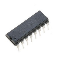
NJM#3517D2 NJR, NJM#3517D2 Datasheet - Page 4

NJM#3517D2
Manufacturer Part Number
NJM#3517D2
Description
Motor / Motion / Ignition Controllers & Drivers Stepper
Manufacturer
NJR
Type
Stepper Motor Controllerr
Datasheet
1.NJM3517D2.pdf
(12 pages)
Specifications of NJM#3517D2
Product
Stepper Motor Controllers / Drivers
Operating Supply Voltage
5 V
Supply Current
60 mA
Mounting Style
Through Hole
Package / Case
DIP-16
Lead Free Status / Rohs Status
Lead free / RoHS Compliant
Available stocks
Company
Part Number
Manufacturer
Quantity
Price
DIR — Direction
DIR determines in which direction steps will be taken. Actual direction depends on motor and motor connections.
DIR can be changed at any time, but not simultaneously with STEP, see timing diagram, figure 6.
pulse will correspond to a half step of the motor. HSM can be changed at any time, but not simultaneously with
STEP, see timing diagram, figure 6.
INH — Inhibit
A HIGH level on the INH input,turns off all phase outputs to reduce current consumption.
An internal Power-On Reset circuit connected to V
up, to prevent false stepping.
The output stage consists of four open-collector transistors. The second high-voltage supply contains Darlington
transistors.
The phase outputs are connected directly to the motor as shown in figure 3.
The bi-level pulse generator consists of two monostables with a common RC network.
monostable which turns on the output transistors for a precise period of time:
t
The Ø
phase current is internally inhibited. These outputs are intended to support if it is legal to correctly go from a half-
step mode to a full-step mode without loosing positional information.
Ø
On
A
HSM determines whether the motor will be controlled in full-step or half-step mode. When pulled low, a step-
The internal phase logic generates a trigger pulse every time the phase changes state. The pulse triggers its own
See pulse diagrams, figures 7 through 11.
The NJM3517 can act as a controller IC for 2 driver ICs, the NJM3770A. Use P
RESET
OUTPUT STAGES
PHASE OUTPUT
BI-LEVEL TECHNIQUE
= 0.55 • C
BIPOLAR PHASE LOGIC OUTPUT
and Ø
A
and Ø
B
for I
T
B
• R
0
outputs are generated from the phase logic and inform an external device if the A phase or the B
and I
T
.
1
control of current turnoff.
cc
resets the phase logic and inhibits the outputs during power
A1
and P
B1
for phase control, and
NJM3517


