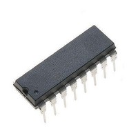
NJM#3517D2 NJR, NJM#3517D2 Datasheet - Page 8

NJM#3517D2
Manufacturer Part Number
NJM#3517D2
Description
Motor / Motion / Ignition Controllers & Drivers Stepper
Manufacturer
NJR
Type
Stepper Motor Controllerr
Datasheet
1.NJM3517D2.pdf
(12 pages)
Specifications of NJM#3517D2
Product
Stepper Motor Controllers / Drivers
Operating Supply Voltage
5 V
Supply Current
60 mA
Mounting Style
Through Hole
Package / Case
DIP-16
Lead Free Status / Rohs Status
Lead free / RoHS Compliant
Available stocks
Company
Part Number
Manufacturer
Quantity
Price
Figure 7. Full-step mode, forward. 4-step sequence. Gray-code
+90 phase shift.
Figure 9. Half-step mode, forward. 8-step sequence.
Figure 11. Half-step mode, inhibit.
Logic inputs
If any of the logic inputs are left open, the circuit will treat it as a high-level input. Unused inputs should be con-
nected to proper voltage levels in order to get the highest noise immunity.
Phase outputs
Phase outputs use a current-sinking method to drive the windings in a unipolar way. A common resistor in the
center tap will limit the maximum motor current.
may be omitted if no bi-level is used. The V
unconnected.
Zero outputs
Ø
is inhibited by the half-step-mode circuitry. A pull-up resistor should be used and connected to a suitable supply
voltage (5 kohms for 5V logic). See “Bipolar phase logic output.”
Interference
To avoid interference problems, a good idea is to route separate ground leads to each power supply, where the
only common point is at the NJM3517’s GND pin. Decoupling of V
pull-up resistor at logic inputs will improve level definitions, especially when driven by open-collector outputs.
DIR
INH
HSM
STEP
OB
LB
PB1
PB2
PA1
PA2
LA
OA
DIR
INH
HSM
STEP
OB
LB
PB1
PB2
PA1
PA2
LA
OA
DIR
INH
HSM
STEP
OB
LB
PB1
PB2
PA1
PA2
LA
OA
A
Fast free-wheeling diodes must be used to protect output transistors from inductive spikes.
Series diodes in V
APPLICATIONS INFORMATION
and Ø
H
H
P
P
P
P
P
P
P
H
P
P
P
P
P
P
P
P
P
L
L
L
H
P
P
P
H
H
H
H
P
P
L
L
L
L
C
C
B
, “zero A” and “zero B,” are open-collector outputs, which go high when the corresponding phase output
MM
supply, prevent V
SS
voltage from shorting through the V
SS
pin must not be connected to a lower voltage than V
Figure 10. Half-step mode, reverse. 8-step sequence.
Figure 8. Full-step mode, reverse. 4-step sequence. Gray-
code -90 phase shift.
DIR
INH
HSM
STEP
OB
LB
PB1
PB2
PA1
PA2
LA
OA
DIR
INT
HSM H
STEP P
OB
LB
PB1
PB2
PA1
PA2
LA
OA
P
P
P
P
P
P
P
P
P
L
L
L
L
L
L
P
P
P
P
P
P
L
C
SS
and V
MM
will improve performance. A 5 kohm
MM
power supply. However, these
NJM3517
MM
, but can be left


