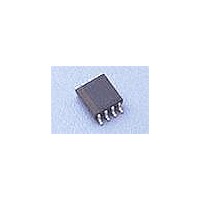
CAT813TZI-GT3 Catalyst / ON Semiconductor, CAT813TZI-GT3 Datasheet - Page 5

CAT813TZI-GT3
Manufacturer Part Number
CAT813TZI-GT3
Description
Supervisory Circuits 4.65V Active-High
Manufacturer
Catalyst / ON Semiconductor
Datasheet
1.CAT813TVI-GT3.pdf
(14 pages)
Specifications of CAT813TZI-GT3
Number Of Voltages Monitored
1
Monitored Voltage
3 V, 3.6 V, 5 V
Manual Reset
Resettable
Watchdog
Watchdog
Supply Voltage (max)
5.5 V
Supply Voltage (min)
1.2 V
Supply Current (typ)
17 uA
Maximum Power Dissipation
330 mW
Maximum Operating Temperature
+ 85 C
Mounting Style
SMD/SMT
Package / Case
MSOP-8
Minimum Operating Temperature
- 40 C
Lead Free Status / Rohs Status
Lead free / RoHS Compliant
ELECTRICAL OPERATING CHARACTERISTICS (continued)
Typical values at T
V
Notes:
(3) WDI is internally serviced within the watchdog period if WDI is left open.
(4) The WDI input current is specified as an average input current when the WDI input is driven high or low. The WDI input if connected to a
(5) RESET
© 2010 SCILLC. All rights reserved.
Characteristics subject to change without notice
WATCHDOG INPUT
MANUAL RESET INPUT
POWER-FAIL INPUT
CC
Symbol
V
V
V
V
= 3.3V for the CAT706 T/S versions; V
three-stated output device can be disabled in the tristate mode as long as the leakage current is less than 10µA and a maximum
capacitance of less than 200pF. To clock the WDI input in the active mode the drive device must be able to source or sink at least 200µA
when active.
¯¯¯¯¯¯ for CAT705 & CAT706 & RESET for CAT813.
t
PDLY
t
t
V
V
V
W_OH
W_OL
V
t
P_OH
P_OL
WD
WP
PB
IH
IH
IL
IL
Parameter
Watchdog Timeout Period
WDI Pulse Width
WDI Input Voltage
WDI Input Current
WDO Output Voltage
¯¯¯ Input Voltage
¯¯¯ Pull-up Current
¯¯¯ Pulse Width
¯¯¯ low to Reset Delay
MR
MR
MR
MR
PFI Input Threshold
PFI Input Current
¯¯¯¯ Output Voltage
PFO
A
= 25°C and V
(4)
(3)
CC
= 5V for CAT705, CAT706, and CAT813 versions;
(5)
CC
Conditions
V
WDI = V
WDI = 0V, Time Average
V
I
4.5 V < V
I
V
I
4.5 V < V
I
¯¯¯ = 0 V
MR
= 3.0V for the CAT706 R version.
V
V
I
4.5 V < V
I
V
I
4.5 V < V
I
SOURCE
SOURCE
SINK
SINK
SOURCE
SOURCE
SINK
SINK
IL
RST (max)
RST (max)
CC
RST (max)
RST (max)
= 0.4 V, V
= +500 µA
= 1.2 mA
= 5 V
= +1.2 mA
= 3.2 mA
= -500 µA
= -800 µA
= -500 µA
= -800 µA
CC
< V
< V
CC
CC
< V
< V
CC
CC
, Time Average
< 5.5 V,
< 5.5 V,
CC
CC
< 5.5 V,
< 5.5 V,
CC
CC
IH
5
< 3.6 V
< 3.6 V,
= 0.8 x V
< 3.6 V,
< 3.6 V,
CC
V
0.7 x V
0.8 x V
V
0.7 x V
0.8 x V
CC
CC
1.00
-150
Min
1.2
-25
50
40
- 1.5V
1
– 1.5
CC
CC
CC
CC
CAT705, CAT706, CAT813
V
CC
1.25
0.01
Typ
1.6
-50
0.1
50
70
– 0.25
0.3 x V
0.3 x V
Doc. No. MD-3030, Rev. E
Max
2.25
150
140
0.3
0.4
1.3
0.4
0.3
0.4
25
5
CC
CC
Units
µA
µA
nA
ns
µs
µs
V
V
V
V
V
s


