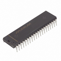
DS2181A Maxim Integrated Products, DS2181A Datasheet - Page 12

DS2181A
Manufacturer Part Number
DS2181A
Description
IC TXRX CEPT PRIMARY RATE 40-DIP
Manufacturer
Maxim Integrated Products
Type
Transceiverr
Datasheet
1.DS2181A.pdf
(32 pages)
Specifications of DS2181A
Number Of Drivers/receivers
1/1
Protocol
CEPT
Voltage - Supply
4.5 V ~ 5.5 V
Mounting Type
Through Hole
Package / Case
40-DIP (0.600", 15.24mm)
Lead Free Status / RoHS Status
Contains lead / RoHS non-compliant
Available stocks
Company
Part Number
Manufacturer
Quantity
Price
Part Number:
DS2181A
Manufacturer:
N/A
Quantity:
20 000
Company:
Part Number:
DS2181A+
Manufacturer:
Maxim Integrated Products
Quantity:
135
Part Number:
DS2181A+
Manufacturer:
DALLAS
Quantity:
20 000
Company:
Part Number:
DS2181AQ
Manufacturer:
Dallas
Quantity:
5 631
Part Number:
DS2181AQ
Manufacturer:
DALLAS
Quantity:
20 000
Company:
Part Number:
DS2181AQ+
Manufacturer:
Maxim Integrated Products
Quantity:
135
Company:
Part Number:
DS2181AQ+
Manufacturer:
Maxim
Quantity:
28
Company:
Part Number:
DS2181AQ+T&R
Manufacturer:
Maxim Integrated
Quantity:
10 000
Company:
Part Number:
DS2181AQ/T&R
Manufacturer:
Maxim Integrated
Quantity:
10 000
FIXED FRAME RESYNC CRITERIA
When enabled via RCR.1, the device will automatically initiate frame search whenever the frame
alignment word is received in error three consecutive times.
FIXED CAS MULTIFRAME RESYNC CRITERIA
When enabled via RCR.1, the device will automatically initiate frame search whenever two consecutive
CAS multiframe alignment words are received in error.
FIXED CRC4 RESYNC CRITERIA
If CCR.1=1 or if the TEST pin is tied high, then the DS2181A will initiate the resync at the FAS level if
915 or more CRC4 words out of 1000 are received in error.
CAS SIGNALLING SOURCE
CAS applications sample signaling data at TSER when TCR.6 = 0; an on-chip data multiplexer accepts
channel-associated data input at TSD when TCR.6 = 1. The data multiplexer must be disabled (TCR.6 =
0) when the CCS mode is enabled (TCR.5 = 1).
TSD INPUT TIMING (TCR.6 = 1; TCR.5 = 0) Table 6
NOTE:
1. A, B, C and D data is sampled on falling edges of TCLK during bit times 5, 6, 7 and 8 of timeslots
FRAME #
indicated.
10
11
12
13
14
15
0
1
2
3
4
5
6
7
8
9
DATA SAMPLED AT TSD
TIMESLOT SIGNALING
11, 28
12, 29
13, 30
14, 31
1, 18
2, 19
3, 20
4, 21
5, 22
6, 23
7, 24
8, 25
9, 26
0, 27
17
15
12 of 32
DS2181A


