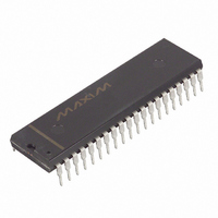
DS2181A Maxim Integrated Products, DS2181A Datasheet - Page 21

DS2181A
Manufacturer Part Number
DS2181A
Description
IC TXRX CEPT PRIMARY RATE 40-DIP
Manufacturer
Maxim Integrated Products
Type
Transceiverr
Datasheet
1.DS2181A.pdf
(32 pages)
Specifications of DS2181A
Number Of Drivers/receivers
1/1
Protocol
CEPT
Voltage - Supply
4.5 V ~ 5.5 V
Mounting Type
Through Hole
Package / Case
40-DIP (0.600", 15.24mm)
Lead Free Status / RoHS Status
Contains lead / RoHS non-compliant
Available stocks
Company
Part Number
Manufacturer
Quantity
Price
Part Number:
DS2181A
Manufacturer:
N/A
Quantity:
20 000
Company:
Part Number:
DS2181A+
Manufacturer:
Maxim Integrated Products
Quantity:
135
Part Number:
DS2181A+
Manufacturer:
DALLAS
Quantity:
20 000
Company:
Part Number:
DS2181AQ
Manufacturer:
Dallas
Quantity:
5 631
Part Number:
DS2181AQ
Manufacturer:
DALLAS
Quantity:
20 000
Company:
Part Number:
DS2181AQ+
Manufacturer:
Maxim Integrated Products
Quantity:
135
Company:
Part Number:
DS2181AQ+
Manufacturer:
Maxim
Quantity:
28
Company:
Part Number:
DS2181AQ+T&R
Manufacturer:
Maxim Integrated
Quantity:
10 000
Company:
Part Number:
DS2181AQ/T&R
Manufacturer:
Maxim Integrated
Quantity:
10 000
RIMR: RECEIVE INTERRUPT MASK REGISTER Figure 19
(MSB)
ALARM REPORTING AND INTERRUPT SERVICING
Alarm and error conditions are reported at outputs and the RSR. Use of the RSR and error count registers
simplifies system error monitoring. The RSR can be read in one of two ways: a burst read does not
disturb the RSR contents; a direct read will clear all bits set in the RSR unless the alarm condition which
set them is still active. Interrupts are enabled via the RIMR and are generated whenever an alarm or error
condition sets an RSR bit. The host controller must service the transceiver in order to clear an interrupt
condition. Clearing the appropriate RIMR bit will unconditionally clear an interrupt.
BVCR: BIPOLAR VIOLATION COUNT REGISTER Figure 20
(MSB)
SYMBOL
SYMBOL
MFSERR
BVD7
RDMA
FSERR
RRA
RUA1
BVD7
BVD0
RLOS
RSA1
RRA
ECS
RDMA
BVD6
POSITION
POSITION
BVCR.7
BVCR.0
RIMR.7
RIMR.6
RIMR.5
RIMR.4
RIMR.3
RIMR.2
RIMR.1
RIMR.0
BVD5
RSA1
NAME AND DESCRIPTION
Receive Remote Alarm
1 = Interrupt enabled
0 = Interrupt masked
Receive Distant Multiframe Alarm
1 = Interrupt enabled
0 = Interrupt masked
Receive Signaling All 1’s
1 = Interrupt enabled
0 = Interrupt masked
Receive Unframed All 1’s
1 = Interrupt enabled
0 = Interrupt masked
Frame Resync Criteria Met
1 = Interrupt enabled
0 = Interrupt masked
CAS Multiframe Resync Criteria Met
1 = Interrupt enabled
0 = Interrupt masked
Receive Loss of Sync
1 = Interrupt enabled
0 = Interrupt masked
Error Count Saturation
1 = Interrupt enabled
0 = Interrupt masked
NAME AND DESCRIPTION
MSB of bipolar violation count.
LSB of bipolar violation count.
RUA1
BVD4
21 of 32
FSERR
BVD3
MFSERR
BVD2
BVD1
RLOS
(LSB)
(LSB)
BVD0
DS2181A
ECS


