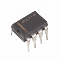
DS275 Maxim Integrated Products, DS275 Datasheet - Page 3

DS275
Manufacturer Part Number
DS275
Description
IC TXRX LINE-PWR RS232 8-DIP
Manufacturer
Maxim Integrated Products
Type
Transceiverr
Datasheet
1.DS275.pdf
(8 pages)
Specifications of DS275
Number Of Drivers/receivers
1/1
Protocol
RS232
Voltage - Supply
4.5 V ~ 5.5 V
Mounting Type
Through Hole
Package / Case
8-DIP (0.300", 7.62mm)
Lead Free Status / RoHS Status
Contains lead / RoHS non-compliant
Available stocks
Company
Part Number
Manufacturer
Quantity
Price
Company:
Part Number:
DS275
Manufacturer:
DALLAS
Quantity:
5 510
Company:
Part Number:
DS2751E
Manufacturer:
MAXIM
Quantity:
361
Part Number:
DS2751E
Manufacturer:
MAXIM/美信
Quantity:
20 000
Part Number:
DS2751E+TR
Manufacturer:
MAXIM/美信
Quantity:
20 000
Part Number:
DS2751E/T
Manufacturer:
MAXIM/美信
Quantity:
20 000
Part Number:
DS2751R
Manufacturer:
MAXIM/美信
Quantity:
20 000
Part Number:
DS2756E
Manufacturer:
MAXIM/美信
Quantity:
20 000
Company:
Part Number:
DS275E
Manufacturer:
SIPEX
Quantity:
6 851
volts, and in many situations it can be tied directly to the +5 volt V
V
The voltage range on V
when TX
happen in a battery-backed condition), only a small leakage current (about 50-100 nA) will be drawn. If
TX
During normal operation (V
course, when TX
upon its voltage and the impedance that TX
The TX
In the event TX
damage, even if continuously shorted.
RS-232 COMPATIBILITY
The intent of the DS275 is not so much to meet all the requirements of the RS-232 specification as to
offer a low-power solution that will work with most RS-232 ports with a connector length of less than 10
feet. As a prime example, the DS275 will not meet the RS-232 requirement that the signal levels be at
least 5 volts minimum when terminated by a 3 k = = = = load and V
volts will be present at TX
interpret any voltage over 2 volts as a space, there will be no problem transmitting data.
APPLICATIONS INFORMATION
The DS275 is designed as a low-cost, RS-232-E interface expressly tailored for the unique requirements
of battery-operated handheld products. As shown in the electrical specifications, the DS275 draws
exceptionally low operating and static current. During normal operation when data from the handheld
system is sent from the TX
transitions positively (spacing). This current flows primarily into the RS-232 receiver’s 3-7 k = = = = load at the
other end of the attaching cable. When TX
dramatically since the negative voltage is provided by the transmit signal from the other end of the cable.
This represents a large reduction in overall operating current, since typical RS-232 interface chips use
charge-pump circuits to establish both positive and negative levels at the transmit driver output.
To obtain the lowest power consumption from the DS275, observe the following guidelines. First, to
minimize V
not being transmitted (idle state). This will force TX
Second, V
directly to the system battery, the logic +5 volts can be turned off to achieve the lowest possible power
state.
FULL-DUPLEX OPERATION
The DS275 is intended primarily for half-duplex operation; that is, RX
marking state when transmitting data out TX
duplex with most RS-232-E serial ports since signals swinging between 0 and +5V will usually be
correctly interpreted by an RS-232-E receiver device. The 5-volt swing occurs when TX
swing negative while RX
for the TX
from some negative value (corresponding to RX
DRV
OUT
must be greater than or equal to V
is loaded during such a condition, V
OUT
OUT
DRV
OUT
output is slew rate-limited to less than 30 volts/us in accordance with RS-232 specifications.
DRV
is in a space state. When V
current will drop to less than 100 nA when V
driver’s negative reference. So, transmit mark signals at TX
current when connected to an RS-232 port, always maintain TX
OUT
OUT
should be inadvertently shorted to ground, internal current-limiting circuitry prevents
is spacing, V
DRV
IN
is at a positive voltage, which turns on an internal weak pulldown to ground
permits the use of a 9-volt battery in order to provide a higher voltage level
OUT
CC
OUT
=5 volts), V
when spacing. However, since most RS-232 receivers will correctly
output, the DS275 only draws significant V
DRV
CC
will draw substantially more current = = = = about 3 mA, depending
CC
at all times.
OUT
OUT
is shut off to the DS275 and V
DRV
DRV
OUT
sees.
is marking (a negative data signal), the V
will draw current only if RX
will draw less than 2 uA when TX
and visa versa. However, the part can be operated full-
3 of 8
IN
OUT
marking) to approximately ground. One possible
into the marking state, minimizing V
CC
DRV
is grounded. Therefore, if V
CC
= +5 volts. Typically a voltage of 4
supply. It is important to note that
DRV
IN
OUT
IN
should remain idle in the
IN
is still powered (as might
DRV
is not in a negative state.
may have voltage jumps
at a logic 1 when data is
current when TX
OUT
DRV
is marking. Of
OUT
current falls
DRV
attempts to
DRV
current.
is tied
DS275
OUT


