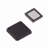
ADV7393BCPZ Analog Devices Inc, ADV7393BCPZ Datasheet - Page 59

ADV7393BCPZ
Manufacturer Part Number
ADV7393BCPZ
Description
IC DAC VIDEO HDTV 10BIT 40LFCSP
Manufacturer
Analog Devices Inc
Type
Video Encoderr
Datasheet
1.ADV7393BCPZ.pdf
(108 pages)
Specifications of ADV7393BCPZ
Design Resources
Reconstruction Video Filter Using ADA4430-1 Amplifier After ADV7393 Video Encoder (CN0101)
Applications
Set-Top Boxes, Video Players, Displays
Voltage - Supply, Analog
2.6 V ~ 3.46 V
Voltage - Supply, Digital
1.71 V ~ 1.89 V
Mounting Type
Surface Mount
Package / Case
40-LFCSP
Input Format
Digital
Output Format
Analog
Supply Voltage Range
1.71V To 1.89V
Operating Temperature Range
-40°C To +85°C
Tv / Video Case Style
LFCSP
No. Of Pins
40
Msl
MSL 1 - Unlimited
Lead Free Status / RoHS Status
Lead free / RoHS Compliant
For Use With
ADV7393-DBRDZ - BOARD EVAL FOR ADV7393EVAL-ADV7393EBZ - BOARD EVAL FOR ADV7393 ENCODER
Lead Free Status / RoHS Status
Lead free / RoHS Compliant, Lead free / RoHS Compliant
Available stocks
Company
Part Number
Manufacturer
Quantity
Price
Company:
Part Number:
ADV7393BCPZ
Manufacturer:
SIEMENS
Quantity:
101
Part Number:
ADV7393BCPZ
Manufacturer:
ADI/亚德诺
Quantity:
20 000
Company:
Part Number:
ADV7393BCPZ-3
Manufacturer:
ADI
Quantity:
302
Part Number:
ADV7393BCPZ-3
Manufacturer:
ADI/亚德诺
Quantity:
20 000
Company:
Part Number:
ADV7393BCPZ3
Manufacturer:
OSRAM
Quantity:
4 298
The reset value of the control registers is 0x00; that is, nominal
DAC current is output. Table 51 is an example of how the output
current of the DACs varies for a nominal 4.33 mA output current.
Table 51. DAC Gain Control
Subaddress 0x0B
0100 0000 (0x40)
0011 1111 (0x3F)
0011 1110 (0x3E)
...
...
0000 0010 (0x02)
0000 0001 (0x01)
0000 0000 (0x00)
1111 1111 (0xFF)
1111 1110 (0xFE)
...
...
1100 0010 (0xC2)
1100 0001 (0xC1)
1100 0000 (0xC0)
GAMMA CORRECTION
Subaddress 0x44 to Subaddress 0x57 for ED/HD;
Subaddress 0xA6 to Subaddress 0xB9 for SD
Generally, gamma correction is applied to compensate for the
nonlinear relationship between signal input and output
brightness level (as perceived on a CRT). It can also be applied
wherever nonlinear processing is used.
Gamma correction uses the function
where γ is the gamma correction factor.
Gamma correction is available for SD and ED/HD video. For
both variations, there are twenty 8-bit registers. They are used
to program Gamma Correction Curve A and Gamma
Correction Curve B.
ED/HD gamma correction is enabled using Subaddress 0x35,
Bit 5. ED/HD Gamma Correction Curve A is programmed at
Subaddress 0x44 to Subaddress 0x4D, and ED/HD Gamma
Correction Curve B is programmed at Subaddress 0x4E to
Subaddress 0x57.
SD gamma correction is enabled using Subaddress 0x88, Bit 6.
SD Gamma Correction Curve A is programmed at Subaddress
0xA6 to Subaddress 0xAF, and SD Gamma Correction Curve B
is programmed at Subaddress 0xB0 to Subaddress 0xB9.
Signal
OUT
= ( Signal
DAC Current
(mA)
4.658
4.653
4.648
...
...
4.43
4.38
4.33
4.25
4.23
...
...
4.018
4.013
4.008
IN
)
γ
% Gain
7.5000%
7.3820%
7.3640%
...
...
0.0360%
0.0180%
0.0000%
−0.0180%
−0.0360%
...
...
−7.3640%
−7.3820%
−7.5000%
Note
Reset value,
nominal
Rev. B | Page 59 of 108
Gamma correction is performed on the luma data only. The
user can choose one of two correction curves, Curve A or
Curve B. Only one of these curves can be used at a time. For
ED/HD gamma correction, curve selection is controlled using
Subaddress 0x35, Bit 4. For SD gamma correction, curve
selection is controlled using Subaddress 0x88, Bit 7.
The shape of the gamma correction curve is controlled by
defining the curve response at 10 different locations along the
curve. By altering the response at these locations, the shape of
the gamma correction curve can be modified. Between these
points, linear interpolation is used to generate intermediate
values. Considering the curve to have a total length of 256
points, the 10 programmable locations are at the following
points: 24, 32, 48, 64, 80, 96, 128, 160, 192, and 224. The
following locations are fixed and cannot be changed: 0, 16, 240,
and 255.
From the curve locations, 16 to 240, the values at the program-
mable locations and, therefore, the response of the gamma
correction curve, should be calculated to produce the following
result:
where:
x
x
γ is the gamma correction factor.
To program the gamma correction registers, calculate the
10 programmable curve values using the following formula:
where:
γ
for point n on the gamma correction curve.
n = 24, 32, 48, 64, 80, 96, 128, 160, 192, or 224.
γ is the gamma correction factor.
For example, setting γ = 0.5 for all programmable curve data
points results in the following y
where the sum of each equation is rounded to the nearest integer.
DESIRED
INPUT
n
is the value to be written into the gamma correction register
ADV7390/ADV7391/ADV7392/ADV7393
x
y
y
y
y
y
y
y
y
y
y
γ
DESIRED
24
32
48
64
80
96
128
160
192
224
is the linear input signal.
n
is the desired gamma corrected output.
= [(8/224)
= [(16/224)
= [(32/224)
= [(48/224)
= [(64/224)
= [(80/224)
=
= [(112/224)
= [(144/224)
= [(176/224)
= [(208/224)
⎛
⎜
⎜
⎝
⎛
⎜
⎝
= ( x
240
n
−
INPUT
−
16
0.5
16
0.5
0.5
0.5
0.5
0.5
)
× 224] + 16 = 58
⎞
⎟
⎠
0.5
0.5
0.5
0.5
γ
× 224] + 16 = 76
× 224] + 16 = 101
× 224] + 16 = 120
× 224] + 16 = 136
× 224] + 16 = 150
γ
× 224] + 16 = 174
× 224] + 16 = 214
× 224] + 16 = 232
× 224] + 16 = 195
×
(
240
−
n
16
values:
)
⎞
⎟
⎟
⎠
+
16


