CKD510JB1H220ST TDK Corporation, CKD510JB1H220ST Datasheet - Page 10
CKD510JB1H220ST
Manufacturer Part Number
CKD510JB1H220ST
Description
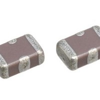
Multilayer Ceramic Capacitors (MLCC) - SMD/SMT 22pf 50volt +50-20% 2.0x1.25x0.85mm
Manufacturer
TDK Corporation
Datasheet
1.CKD510JB1H220ST.pdf
(17 pages)
Specifications of CKD510JB1H220ST
Capacitance
22 pF
Tolerance
- 20 %, 50 %
Voltage Rating
50 Volts
Operating Temperature Range
- 55 C to + 85 C
Product
General Type MLCCs
Dimensions
1.25 mm W x 2 mm L
Termination Style
SMD/SMT
Lead Free Status / Rohs Status
Details
Other names
CKD510JB1H220S
Available stocks
Company
Part Number
Manufacturer
Quantity
Price

Part Number:
CKD510JB1H220ST
Manufacturer:
TDK/东电化
Quantity:
20 000
Company:
Part Number:
CKD510JB1H220ST000A
Manufacturer:
TDK
Quantity:
4 150
Company:
Part Number:
CKD510JB1H220ST000N
Manufacturer:
TDK
Quantity:
4 150


TDK MLCC US Catalog
No.
9
10
11
General
Specifications
Item
Resistance to solder heat
External
appearance
Capacitance
D.F. (Class 2)
Insulation
Resistance
Voltage
Proof
Resistance
for DC (R
Temperature cycle
External
appearance
Capacitance
D.F. (Class 2)
Insulation
Resistance
Resistance
for DC (R
Moisture Resistance (Steady State)
External
appearance
Capacitance
D.F. (Class 2)
Insulation
Resistance
Resistance
for DC (R
dc
dc
dc
)
)
)
Performance
No mechanical damage.
Meet the initial spec.
Meet the initial spec.
No insulation breakdown or other
damage.
1.0 Ω max.
No mechanical damage.
Meet the initial spec.
Meet the initial spec.
1.0 Ω max.
No mechanical damage.
200% of initial spec. max.
1,000MΩ or 50MΩ•μF min, whichever
smaller. (As for the capacitors of rated
voltage 16, 10, 6.3V DC, 10MΩ•μF
min.)
1.0 Ω max.
Change from the value
Change from the value
Change from the value
before test
before test
before test
± 7.5%
± 7.5%
± 12.5%
CKD Series – Feed Through Type
Page 220
Test or Inspection Method
Completely soak both terminations in solder at
260±5ºC for 5±1s.
Preheating condition
Flux: Isopropyl alcohol (JIS K 8839)
Solder: H63A (JIS Z 3282)
Leave the capacitor in ambient conditions for 24±2h
before measurement.
Reflow solder the capacitor on P.C. board (shown in
Appendix 1 or Appendix 3) before testing.
Expose the capacitor in the conditions step1 through
step 4 and repeat 5 times consecutively.
Leave the capacitor in ambient conditions for 24±2h
before measurement.
Reflow solder the capacitors on P.C. board (shown in
Appendix 1 or Appendix 3) before testing.
Leave at temperature 40±2ºC, 90 to 95%RH for 500
+24,0h.
Leave the capacitor in ambient conditions for 24±2h
before measurement.
Step
1
2
3
4
Temp.: 150±10ºC
Time: 1 to 2min.
Rosin (JIS K 5902) 25% solid solution.
Temperature (ºC)
Min. operating temp. ±3
20 ± 2
Max. operating temp. ± 2
20 ± 2
Time (min.)
30 ± 3
2 – 5
30 ± 2
2 - 5
Version B11
Related parts for CKD510JB1H220ST
Image
Part Number
Description
Manufacturer
Datasheet
Request
R

Part Number:
Description:
TDK DC to DC Converters, DC to AC Inverters
Manufacturer:
TDK Corporation
Datasheet:
Part Number:
Description:
TDK DC to DC Converters, DC to AC Inverters
Manufacturer:
TDK Corporation
Datasheet: