CKD510JB1H220ST TDK Corporation, CKD510JB1H220ST Datasheet - Page 15
CKD510JB1H220ST
Manufacturer Part Number
CKD510JB1H220ST
Description
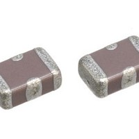
Multilayer Ceramic Capacitors (MLCC) - SMD/SMT 22pf 50volt +50-20% 2.0x1.25x0.85mm
Manufacturer
TDK Corporation
Datasheet
1.CKD510JB1H220ST.pdf
(17 pages)
Specifications of CKD510JB1H220ST
Capacitance
22 pF
Tolerance
- 20 %, 50 %
Voltage Rating
50 Volts
Operating Temperature Range
- 55 C to + 85 C
Product
General Type MLCCs
Dimensions
1.25 mm W x 2 mm L
Termination Style
SMD/SMT
Lead Free Status / Rohs Status
Details
Other names
CKD510JB1H220S
Available stocks
Company
Part Number
Manufacturer
Quantity
Price

Part Number:
CKD510JB1H220ST
Manufacturer:
TDK/东电化
Quantity:
20 000
Company:
Part Number:
CKD510JB1H220ST000A
Manufacturer:
TDK
Quantity:
4 150
Company:
Part Number:
CKD510JB1H220ST000N
Manufacturer:
TDK
Quantity:
4 150


• Recommended Soldering Land Pattern
TDK MLCC US Catalog
Series
Series
CKD510JB, CKD110JB, CKD310JB
CKD710JB
CKD510JB
CKD110JB
CKD310JB
CKD610JB
Symbol
Symbol
Resist
Resist
Soldering
Information
CKD610JB
CKD710JB
c
a
b
c
b
a
0.19
a
b
c
0.5
1.4
1.4
0.4
a
a
Cu Pattern
Cu Pattern
Through hole
Through hole
φ0.4~0.6
Ø0.4-0.6
Through hole
0.7
1.5
2.5
2.5
1.2
b
b
Ø0.4-0.6
d e
d
d
e
e
Connect to the ground pattern of the
chip mounted side.
1.3
2.6
4.5
4.5
2.2
c
c
No Pattern
Back side:
Back side shall be
connected to the
ground pattern of the
chip mounted side.
Please design the
back side ground as
large as possible.
*If through hole is too
big, solder paste may
come into the hole
and make bad
connection with the
ground pattern.
Connect to the
ground pattern of the
chip mounted side.
“Through hole” should
be designed as close
to GND terminal as
possible.
0.6
1.0
1.0
1.2
0.7
d
d
Ground
pattern
0.75
2.0
2.0
2.4
1.4
e
e
CKD Series – Feed Through Type
Page 225
Peak
Temp
0
• Recommended Soldering Profile
• Recommended Solder Amount
∆T
Over 60 sec.
Excessive
solder
Adequate
solder
Insufficient
solder
Solder
Preheating
Recommended soldering duration
Recommended solder compositions
Preheating Condition
Lead-Free Solder
Manual soldering
Reflow soldering
Sn-37Pb (Sn-Pb solder)
Sn-3.0Ag-0.5Cu (Lead Free Solder)
Sn-Pb Solder
Soldering
Method
Reflow Soldering
Peak Temp time
Soldering Natural
Temp./
Dura.
cooling
Peak temp
230 max.
260 max.
(°C)
300
0
Temperature (ºC)
Reflow Soldering
∆T ≤ 150
∆T ≤ 150
∆T
Preheating
Duration
20 max.
10 max.
(sec.)
Manual soldering
3sec. (As short as possible)
Minimum amount
Higher tensile force
on the chip
capacitor may
cause cracking.
Maximum amount
Small solder fillet
may cause contact
failure or failure to
hold the chip
capacitor to the
P.C. board.
(Solder iron)
Version B11
Related parts for CKD510JB1H220ST
Image
Part Number
Description
Manufacturer
Datasheet
Request
R

Part Number:
Description:
TDK DC to DC Converters, DC to AC Inverters
Manufacturer:
TDK Corporation
Datasheet:
Part Number:
Description:
TDK DC to DC Converters, DC to AC Inverters
Manufacturer:
TDK Corporation
Datasheet: