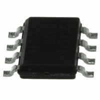
MPR031EPR2 Freescale Semiconductor, MPR031EPR2 Datasheet - Page 16

MPR031EPR2
Manufacturer Part Number
MPR031EPR2
Description
IC CTLR TOUCH SENSOR 8-DFN
Manufacturer
Freescale Semiconductor
Type
Capacitiver
Specifications of MPR031EPR2
Touch Panel Interface
2-Wire
Data Interface
I²C, Serial
Data Rate/sampling Rate (sps, Bps)
400k
Voltage - Supply
1.71 V ~ 2.75 V
Current - Supply
43µA
Operating Temperature
-40°C ~ 85°C
Mounting Type
Surface Mount
Package / Case
8-UDFN
Output Type
Logic
Interface
I²C
Input Type
Logic
Supply Voltage
1.8 V
Output Voltage
0.5 V
Supply Current
8µA
Ic Interface Type
I2C
Supply Voltage Range
1.71V To 2.75V
Sensor Case Style
µDFN
No. Of Pins
8
Operating Temperature Range
-40°C To +85°C
Interface Type
I2C
Rohs Compliant
Yes
For Use With
KITMPR03XEVM - KIT EVAL FOR MPR03XDEMOMPR031 - BOARD DEMO FOR MPR031 CTLR
Lead Free Status / RoHS Status
Lead free / RoHS Compliant
Other names
MPR031EPR2TR
Available stocks
Company
Part Number
Manufacturer
Quantity
Price
Company:
Part Number:
MPR031EPR2
Manufacturer:
INTERSIL
Quantity:
9 912
MPR03X
16
7
7.1
The MPR03X utilizes the principle that a capacitor holds a fixed amount of charge at a specific electric potential. Both the
implementation and the configuration will be described in this section.
7.2
The basic measurement technique used by the MPR03X is to charge up the capacitor C on one electrode input with a DC current
I for a time T (the charge time). Before measurement, the electrode input is grounded, so the electrode voltage starts from 0 V
and charges up with a slope,
are grounded during this measurement. At the end of time T, the electrode voltage is measured with a 10 bit ADC. The voltage
is inversely proportional to capacitance according to
rate it was charged.
When measuring capacitance there are some inherent restrictions due to the methodology used. On the MPR03X the voltage
after charging must be in the range that is shown in
Theory of Operation
Introduction
Capacitance Measurement
V
900
800
700
600
500
400
300
200
100
0
1.71
Figure 21. MPR03X Electrode Measurement Charging Pad Capacitance
Electrode Charge Time
Equation
1, where C is the pad capacitance on the electrode
1.91
Electrode
Charging
V
Figure
dV
Equation 2
dt
Valid ADC Values vs. V DD
=
2.11
I
=
Figure 22.
×
C
22.
V DD (V)
C
ADChigh
ADCmid
ADClow
I
T
T
.
The electrode is then discharged back to ground at the same
Electrode voltage measured here
Discharging
Electrode
2.31
Electrode Discharge Time
2.51
(Figure
21). All of the other electrodes
Freescale Semiconductor
2.71
2T
Equation 1
Equation 2
Sensors


