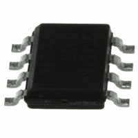
MPR031EPR2 Freescale Semiconductor, MPR031EPR2 Datasheet - Page 4

MPR031EPR2
Manufacturer Part Number
MPR031EPR2
Description
IC CTLR TOUCH SENSOR 8-DFN
Manufacturer
Freescale Semiconductor
Type
Capacitiver
Specifications of MPR031EPR2
Touch Panel Interface
2-Wire
Data Interface
I²C, Serial
Data Rate/sampling Rate (sps, Bps)
400k
Voltage - Supply
1.71 V ~ 2.75 V
Current - Supply
43µA
Operating Temperature
-40°C ~ 85°C
Mounting Type
Surface Mount
Package / Case
8-UDFN
Output Type
Logic
Interface
I²C
Input Type
Logic
Supply Voltage
1.8 V
Output Voltage
0.5 V
Supply Current
8µA
Ic Interface Type
I2C
Supply Voltage Range
1.71V To 2.75V
Sensor Case Style
µDFN
No. Of Pins
8
Operating Temperature Range
-40°C To +85°C
Interface Type
I2C
Rohs Compliant
Yes
For Use With
KITMPR03XEVM - KIT EVAL FOR MPR03XDEMOMPR031 - BOARD DEMO FOR MPR031 CTLR
Lead Free Status / RoHS Status
Lead free / RoHS Compliant
Other names
MPR031EPR2TR
Available stocks
Company
Part Number
Manufacturer
Quantity
Price
Company:
Part Number:
MPR031EPR2
Manufacturer:
INTERSIL
Quantity:
9 912
MPR03X
4
2.3
The MPR03X uses an I
Sensor Controller are detailed in the following sections.
2.3.1
The MPR03X operates as a slave that sends and receives data through an I
Line (SDA) and a Serial Clock Line (SCL) to achieve bi-directional communication between master(s) and slave(s). A master
(typically a microcontroller) initiates all data transfers to and from the MPR03X, and it generates the SCL clock that synchronizes
the data transfer.
The MPR03X SDA line operates as both an input and an open-drain output. A pull-up resistor, typically 4.7kΩ, is required on
SDA. The MPR03X SCL line operates only as an input. A pull-up resistor, typically 4.7kΩ, is required on SCL if there are multiple
masters on the 2-wire interface, or if the master in a single-master system has an open-drain SCL output.
Each transmission consists of a START condition
R/W bit, a register address byte, one or more data bytes, and finally a STOP condition.
2.3.2
Both SCL and SDA remain high when the interface is not busy. A master signals the beginning of a transmission with a
START (S) condition by transitioning SDA from high to low while SCL is high. When the master has finished communicating with
the slave, it issues a STOP (P) condition by transitioning SDA from low to high while SCL is high. The bus is then free for another
transmission.
Serial Interface
Serial-Addressing
Start and Stop Conditions
SDA
SCL
t HD STA
SDA
SCL
CONDIT ION
ST ART
2
C Serial Interface. The I
t LOW
DATA LINE STABLE
t R
DATA VALID
t HIGH
t SU DAT
Figure 5. Wire Serial Interface Timing Details
t F
Figure 6. Start and Stop Conditions
t HD DAT
2
(Figure
C protocol implementation and the specifics of communicating with the Touch
5) sent by a master, followed by the MPR03X’s 7-bit slave address plus
DATA ALLOWED
t SU STA
CHANGE OF
REPEAT ED ST ART
CONDIT ION
2
C 2-wire interface. The interface uses a Serial Data
t HD STA
t SU STO
CONDIT ION
ST OP
Freescale Semiconductor
t BUF
CONDIT ION
ST ART
Sensors


