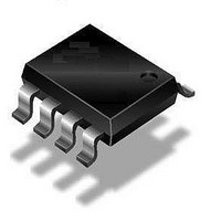
QT115A-ISG Atmel, QT115A-ISG Datasheet - Page 9

QT115A-ISG
Manufacturer Part Number
QT115A-ISG
Description
IC TOUCH SENSOR PROX 8SOIC
Manufacturer
Atmel
Datasheet
1.AT42QT1040-MMH.pdf
(72 pages)
Specifications of QT115A-ISG
Input Type
*
Output Type
*
Interface
*
Current - Supply
*
Mounting Type
Surface Mount
Operating Supply Voltage
3 V to 5 V
Maximum Operating Temperature
+ 85 C
Mounting Style
SMD/SMT
Package / Case
SO-8
Minimum Operating Temperature
- 40 C
Lead Free Status / RoHS Status
Lead free / RoHS Compliant
Package / Case
-
Lead Free Status / Rohs Status
Details
Touch Sensors Design Guide
Capacitance (C) is defined in
Equation 1-1. Capacitance
It should therefore be clear that thinner panels and higher dielectric constant materials yield higher
capacitance change during touch and hence a higher gain and a better SNR.
Materials” on page 2-5
Figure 1-2.
In the context of capacitive sensors, SNR is defined as in
of the touch signal levels.
Equation 1-2. SNR
1. Note that this definition uses the RMS noise present during touch, as this is the worst case.
T
Touchscreen Panel
Touch Area (A)
SNR(dB) = 20Log( TouchStrength / NoiseTouched
TouchStrength = SignalTouched
NoiseTouched
where:
C
AVG100 means the simple numeric average of 100 data points, typically taken evenly
spaced over a period of 2 seconds.
RMS100 means the root-mean-square of 100 data points, typically taken evenly
spaced over a period of 2 seconds, using the AVG100 figure as a baseline.
=
------------------------- -
0
discusses the thickness of the panel and its effect on the SNR.
Overlying Panel ( )
T
r
A
Equation
RMS100
=
e
1-1.
r
n
--------------------------------------------------------------------------------------------------------------------- -
n
=
=
99
0
Signal n SignalTouched
AVG100
- SignalUntouched
–
Equation
100
RMS100
1-2.
Introduction To Sensor Design
(1)
)
AVG100
AVG100
See
Section 2.3.3 “Front Panel
Figure 1-3
2
Sensor
Behind
Panel
10620D–AT42–04/09
for definitions
1-3


