AD2S81AJD Analog Devices Inc, AD2S81AJD Datasheet - Page 13
AD2S81AJD
Manufacturer Part Number
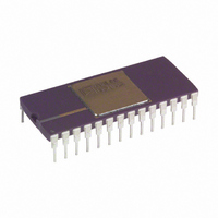
AD2S81AJD
Description
IC R/D CONV TRACKING 28CDIP
Manufacturer
Analog Devices Inc
Type
R/D Converterr
Datasheet
1.AD2S80AJD.pdf
(16 pages)
Specifications of AD2S81AJD
Rohs Status
RoHS non-compliant
Input Type
Parallel
Output Type
Digital
Interface
Parallel
Current - Supply
30mA
Mounting Type
Through Hole
Package / Case
28-CDIP (0.600", 15.24mm)
Resolution (bits)
12bit
Input Channel Type
Parallel
Data Interface
Parallel
Supply Voltage Range - Analog
± 10.8V To ± 13.2V
Supply Current
19mA
Digital Ic Case Style
DIP
No. Of Pins
40
Lead Free Status / RoHS Status
Contains lead / RoHS non-compliant
Available stocks
Company
Part Number
Manufacturer
Quantity
Price


1
SOURCES OF ERRORS
Integrator Offset
Additional inaccuracies in the conversion of the resolver signals
will result from an offset at the input to the integrator as it will
be treated as an error signal. This error will typically be 1 arc
minute over the operating temperature range.
A description of how to adjust from zero offset is given in the
section “COMPONENT SELECTION” and the circuit required
is shown in Figure 1.
Differential Phase Shift
Phase shift between the sine and cosine signals from the resolver
is known as differential phase shift and can cause static error.
Some differential phase shift will be present on all resolvers as a
result of coupling. A small resolver residual voltage (quadrature
voltage) indicates a small differential phase shift. Additional phase
shift can be introduced if the sine channel wires and the cosine
channel wires are treated differently. For instance, different cable
lengths or different loads could cause differential phase shift.
The additional error caused by differential phase shift on the
input signals approximates to
where a = differential phase shift (degrees).
This error can be minimized by choosing a resolver with a small
residual voltage, ensuring that the sine and cosine signals are
handled identically and removing the reference phase shift (see
section “CONNECTING THE RESOLVER”). By taking these
precautions the extra error can be made insignificant.
Under static operating conditions phase shift between the refer-
ence and the signal lines alone will not theoretically affect the
converter’s static accuracy.
However, most resolvers exhibit a phase shift between the signal
and the reference. This phase shift will give rise under dynamic
conditions to an additional error defined by:
For example, for a phase shift of 20 degrees, a shaft rotation of
22 rps and a reference frequency of 5 kHz, the converter will
exhibit an additional error of:
This effect can be eliminated by placing a phase shift in the
reference to the converter equivalent to the phase shift in the
resolver (see section “CONNECTING THE RESOLVER”).
Note: Capacitive and inductive crosstalk in the signal and reference
leads and wiring can cause similar problems.
Reversion error, or side-to-side nonlinearity, is a result of differences in the
up and down rates of the VCO.
b = signal to reference phase shift (degrees).
Shaft Speed (rps) × Phase Shift (Degrees )
Error = 0.53 a × b arc minutes
22 × 20
Reference Frequency
5000
0.088 Degrees
VELOCITY ERRORS
The signal at the INTEGRATOR OUTPUT pin relative to the
ANALOG GROUND pin is an analog voltage proportional to
the rate of change of the input angle. This signal can be used to
stabilize servo loops or in the place of a velocity transducer.
Although the conversion loop of the AD2S80A includes a digital
section there is an additional analog feedback loop around the
velocity signal. This ensures against flicker in the digital posi-
tional output in both dynamic and static states.
A better quality velocity signal will be achieved if the following
points are considered:
1. Protection.
2. Reversion error.
3. Ripple and Noise.
Following the preceding precautions will allow the user to use
the velocity signal in very noisy environments, for example,
PWM motor drive applications. Resolver/converter error curves
may exhibit apparent acceleration/deceleration at a constant
velocity. This results in ripple on the velocity signal of frequency
twice the input rotation.
The velocity signal should be buffered before use.
The reversion error can be nulled by varying one supply rail
relative to the other.
Noise on the input signals to the converter is the major cause of
noise on the velocity signal. This can be reduced to a minimum
if the following precautions are taken:
The resolver is connected to the converter using separate
twisted pair cable for the sine, cosine and reference signals.
Care is taken to reduce the external noise wherever possible.
An HF filter is fltted before the Phase Sensitive Demodulator
(as described in the section HF FILTER).
A resolver is chosen that has low residual voltage, i.e., a small
signal in quadrature with the reference.
Components are selected to operate the AD2S80A with the
lowest acceptable bandwidth.
Feedthrough of the reference frequency should be removed by
a filter on the velocity signal.
Maintenance of the input signal voltages at 2 V rms will
prevent LSB flicker at the positional output. The analog
feedback or hysteresis employed around the VCO and the
intergrator is a function of the input signal levels (see sec-
tion “INTEGRATOR”) .
1
AD2S80A
Related parts for AD2S81AJD
Image
Part Number
Description
Manufacturer
Datasheet
Request
R

Part Number:
Description:
±1.7g Dual-Axis IMEMS Accelerometer Evaluation Board
Manufacturer:
Analog Devices Inc
Datasheet:

Part Number:
Description:
Inertial Sensor Evaluation System
Manufacturer:
Analog Devices Inc
Datasheet:
Part Number:
Description:
Manufacturer:
Analog Devices Inc
Datasheet:
Part Number:
Description:
Manufacturer:
Analog Devices Inc
Datasheet:
Part Number:
Description:
Manufacturer:
Analog Devices Inc
Datasheet:
Part Number:
Description:
Manufacturer:
Analog Devices Inc
Datasheet:
Part Number:
Description:
Manufacturer:
Analog Devices Inc
Datasheet:
Part Number:
Description:
Manufacturer:
Analog Devices Inc
Datasheet:
Part Number:
Description:
Manufacturer:
Analog Devices Inc
Datasheet:
Part Number:
Description:
Manufacturer:
Analog Devices Inc
Datasheet:
Part Number:
Description:
Manufacturer:
Analog Devices Inc
Datasheet:
Part Number:
Description:
Manufacturer:
Analog Devices Inc
Datasheet:
Part Number:
Description:
Manufacturer:
Analog Devices Inc
Datasheet: