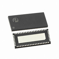
PI3PCIE2612-AZFE Pericom Semiconductor, PI3PCIE2612-AZFE Datasheet - Page 15

PI3PCIE2612-AZFE
Manufacturer Part Number
PI3PCIE2612-AZFE
Description
IC 6CH DISPLAY MUX 56WQFN
Manufacturer
Pericom Semiconductor
Type
MUXr
Datasheet
1.PI3PCIE2612-AZFE.pdf
(18 pages)
Specifications of PI3PCIE2612-AZFE
Tx/rx Type
DisplayPort
Delay Time
200ns
Capacitance - Input
3pF
Voltage - Supply
3 V ~ 3.6 V
Current - Supply
2.5mA
Mounting Type
Surface Mount
Package / Case
56-WQFN
Operating Temperature (min)
-40C
Operating Temperature (max)
85C
Operating Temperature Classification
Industrial
Mounting
Surface Mount
Lead Free Status / RoHS Status
Lead free / RoHS Compliant
Available stocks
Company
Part Number
Manufacturer
Quantity
Price
Company:
Part Number:
PI3PCIE2612-AZFE
Manufacturer:
Pericom
Quantity:
663
Part Number:
PI3PCIE2612-AZFE
Manufacturer:
PERICOM
Quantity:
20 000
Switch Signal Integrity Requirements and Test Procedures for 5.0 Gb/s
Signal integrity requirements for 5.0 Gb/s applications of the switch are specifi ed. Also included are the requirements of
the test fi xture for switch S-parameter measurements.
Signal Integrity Requirements
The procedures outlined in ANSI Electronics Industry Alliance (EIA) standards documents shall be followed:
• EIA 364-101 – Attenuation Test Procedure for Electrical Connectors, Sockets, Cable Assemblies or Interconnection
Systems
• EIA 364-90 – Crosstalk Ratio Test Procedure for Electrical Connectors, Sockets, Cable Assemblies or Interconnection
Systems
• EIA 364-108- Impedance, Refl ection Coeffi cient, Return Loss, and VSWR Measured in the Time and Frequency Do-
main Test Procedure for Electrical Connectors, Sockets, Cable Assemblies or Interconnection Systems
Signal Integrity Requirements and Test Procedures for 5.0 Gb/s
Notes:
1. The specifi ed S parameters requirements are for switch component only, not including the test fi xture effect. While the TRL calibration method is
recommended, other calibration methods are allowed.
Parameter
Differential
Insertion Loss
(DDIL)
Differential
Return Loss
(DDRL)
Intra-pair Skew
Differential Near
End Crosstalk
(DDNEXT)
Differential
Insertion Loss
(DDIL) when
switch is turned
off
08-0145
Procedure
EIA 364-101
The EIA standard shall be used with the following considerations:
1. The measured differential S parameter shall be referenced to a
100 ohms differential impedance.
2. The test fi xture shall meet the test fi xture requirement defi ned in
Section 1.12.
3. The test fi xture effect shall be removed from the measured S
parameters. Refer to Note 1.
EIA 364-108
The EIA standard shall be used with the following considerations:
1. The measured differential S parameter shall be referenced to a
100 ohms differential impedance.
2. The test fi xture shall meet the test fi xture requirement in Section
1.12.
3. The test fi xture effect shall be removed. Refer to Note 1.
Intra-pair skew must be achieved by design; measurement not
required.
EIA 364-90
The EIA standard must be used with the following considerations:
1. The crosstalk requirement is with respect to all the adjacent dif-
ferential pairs
EIA 364-101
15
1:2 DP/PCIe Gen2 Display Mux, ATX Pinout
High Bandwidth, 6-Differential Channel
Requirements
≥-[0.6*(f)+0.5] dB up to 2.5 GHz (for
example, ≥-2 dB at f = 2.5 GHz);
≥-[1.2*(f-2.5)+2] dB for 2.5 GHz < f ≤ 5
GHz (for example, ≥-5 dB at f = 5 GHz);
≥-[1.6*(f-5)+5] dB for 5 GHz < f ≤ 7.5
GHz (for example, ≥-9 dB at f = 7.5
GHz);
Refer to Figure 1.
≤ -14 dB up to 2.8 GHz; ≤ -8 dB up to 5
GHz; ≤ -4 dB up to 7.5 GHz.
Refer to Figure 2.
5 ps max
-32 dB max up to 2.5 GHz;
-26 dB max up to 5.0 GHz;
-20 dB max up to 7.5 GHz;
See Figure 3.
≤ -20 dB up to 3 GHz;
PI3PCIE2612-A
PS8925D
07/31/08


