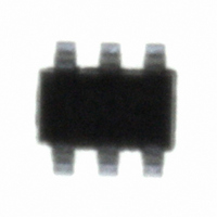
LX7202-15ISF Microsemi Analog Mixed Signal Group, LX7202-15ISF Datasheet - Page 4

LX7202-15ISF
Manufacturer Part Number
LX7202-15ISF
Description
IC USB LINE TERM EMI/ESD SOT23-6
Manufacturer
Microsemi Analog Mixed Signal Group
Type
USBr
Datasheet
1.LX7202-15ISF.pdf
(7 pages)
Specifications of LX7202-15ISF
Number Of Terminations
2
Voltage - Supply
5.25V
Operating Temperature
-40°C ~ 125°C
Mounting Type
Surface Mount
Package / Case
SOT-23-6
Lead Free Status / RoHS Status
Contains lead / RoHS non-compliant
Copyright © 2002
Rev. 1.0d, 2007-04-11
L
transfer rate known as Low-Speed which requires a 1.5 k Ω
pull-up resistor to be connected to the D- line. Slew rate
control is accomplished with 47pF attached to the
transceiver before the R
FCC Part 15 sets limits for maximum allowable EM
emission and susceptibility. There are two types of
emissions.
emission of 0.45 to 30 MHz and Radiated emissions with
frequency of emission of 30 MHz to 40 GHz. All digital
computing devices including the peripheral devices must
comply. Examples of peripheral devices include terminals,
printers, external floppy disk drives and other fixed
adjustable data storage devices, video monitors, keyboards,
OW
The USB v1.1 specification offers a 1.5 Mbps data
S
PEED
Transceiver
TM
Host
USB
D
EVICE
Conducted emissions with frequency of
cable
S
.
11861 Western Avenue, Garden Grove, CA. 92841, 714-898-8121, Fax: 714-893-2570
ELECTROMAGNETIC EMISSION AND SUSCEPTABILITY
A P P L I C A T I O N I N F O R M A T I O N ( C O N T I N U E D )
GND
V
BUS
D+
D-
Figure 3 – Connection for Low Speed Operation
Analgo Mixed Signal Group
®
Microsemi
V
D
D
BUS
IN
IN
1
2
3
EMI Filter & ESD Protection for Up Stream USB
cards and other input/output devices that may or may not
contain digital circuitry. LX7202 is optimized to minimize
the radiated EMI which is the primary concern in devices
using USB. Refer to the typical filter response curve for
the attenuation characteristics of LX7202 over the
frequency range of 30KHz to 6GHz.
control cards, interface boards, external memory expansion
the D+ line of the USB Transceiver
up resistor) and Pin 4 to the D- line of the USB Transceiver
LX7202
R
PU
Voltage Supply (Vbus) is connected to Pin 1
Ground is connected to Pin 6
D+ from the connector is routed to Pin 2 and Pin 5 to
D- from the connector is routed to Pin 3 (1.5 kΩ pull-
P
RODUCTION
6
5
4
GND
D
D
OUT
OUT
Ports
D
ATA
S
Transceiver
GND
V
D-
D+
HEET
Peripheral
BUS
USB
LX7202-xx
Page 4


