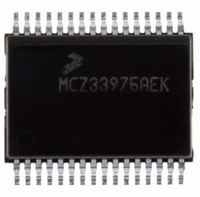
MCZ33975AEK Freescale Semiconductor, MCZ33975AEK Datasheet - Page 22

MCZ33975AEK
Manufacturer Part Number
MCZ33975AEK
Description
IC MULTIPLE SWITCH DETECT 32SOIC
Manufacturer
Freescale Semiconductor
Datasheet
1.MCZ33975AEK.pdf
(34 pages)
Specifications of MCZ33975AEK
Applications
Automotive
Interface
SPI
Voltage - Supply
5.5 V ~ 28 V
Package / Case
32-SOIC (7.5mm Width) Exposed Pad, 32-eSOIC, 32-HSOIC
Mounting Type
Surface Mount
Lead Free Status / RoHS Status
Lead free / RoHS Compliant
Sleep Mode only with a valid sleep command.
SLEEP MODE
Sleep Mode may be entered only by sending the sleep
command. All register settings programmed in Normal Mode
will be maintained in Sleep Mode.
when any of the following events occur:
When the timer expires, an interrupt is generated and the
device enters Normal Mode.
disabled by programming the interrupt bits to logic [1 1 1].
timer.
switch reads in Sleep Mode. The period is set in the sleep
command and may be set to 000 (no period) to 111 (64ms).
In Sleep Mode when the scan timer expires, inputs will
behave as programmed prior to sleep command. The 33975
will wake up for approximately 125μs and read the switch
inputs. At the end of the 125μs, the input switch states are
compared with the switch state prior to sleep command.
When switch state changes are detected, an interrupt (when
enabled; refer to wake-up/interrupt command description on
page
Without switch state changes, the 33975 will reset the scan
timer, inputs become tri-state, and the Sleep Mode continues
until the scan timer expires again.
timer.
Normal Mode.
22
33975
Table 18. Sleep Command
FUNCTIONAL DEVICE OPERATION
OPERATIONAL MODES
23
0
The 33975 device will exit the Normal Mode and enter the
Sleep Mode is used to reduce system quiescent currents.
The 33975 will exit Sleep Mode and enter Normal Mode
• Input switch change of state (when enabled)
• Interrupt timer expire
• Falling edge of
The interrupt timer is used as a periodic wake-up timer.
Note: The interrupt timer in the 33975 device may be
Table 19
The scan timer sets the polling period between input
Table 20
Note: The interrupt and scan timers are disabled in the
17) is generated and the device enters Normal Mode.
22
0
shows the programmable settings of the Interrupt
shows the programmable settings of the Scan
21
0
Sleep Command
20
0
WAKE
19
1
18
1
17
0
16
0
15
X
14
X
13
X
12
X
11
X
Sleep Mode. However removing VDD from the device in
Sleep Mode will disable a wake-up from falling edge of
and
first SO data message is not valid.
programmable timers for Sleep Mode, the interrupt timer and
the scan timer, as shown in
• Falling edge of
• Falling edge of
• Power-on reset (POR)
The VDD supply may be removed from the device during
Note: In cases where
The sleep command contains settings for two
10
X
CS
Logic [1])
.
Table 19. Interrupt Timer
Table 20. Scan Timer
X
9
Command Bits
Bits 543
Bits 210
000
001
010
011
100
101
110
111
000
001
010
011
100
101
110
111
X
8
X
7
INT
CS
Analog Integrated Circuit Device Data
(with VDD = 5.0V)
(with VDD = 5.0V and
CS
6
X
No interrupt wake-up
Table
is used to wake the device, the
Interrupt Period
5
Scan Period
No Scan
128ms
256ms
512ms
1.024s
2.048s
1.0ms
2.0ms
4.0ms
8.0ms
18.
32ms
64ms
16ms
32ms
64ms
Freescale Semiconductor
4
3
2
WAKE
1
at
INT
0


