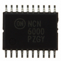
NCN6000DTBR2 ON Semiconductor, NCN6000DTBR2 Datasheet - Page 31

NCN6000DTBR2
Manufacturer Part Number
NCN6000DTBR2
Description
IC INTERFACE SMART CARD 20TSSOP
Manufacturer
ON Semiconductor
Datasheet
1.NCN6000DTBR2.pdf
(36 pages)
Specifications of NCN6000DTBR2
Applications
ATM Terminals, Gas Pumps, ISM
Interface
Microcontroller
Voltage - Supply
2.7 V ~ 6 V
Package / Case
20-TSSOP
Mounting Type
Surface Mount
Lead Free Status / RoHS Status
Contains lead / RoHS non-compliant
Other names
NCN6000DTBR2OSTR
Available stocks
Company
Part Number
Manufacturer
Quantity
Price
Part Number:
NCN6000DTBR2
Manufacturer:
ON/安森美
Quantity:
20 000
Part Number:
NCN6000DTBR2G
Manufacturer:
ON/安森美
Quantity:
20 000
Security Features
card, the NCN6000 provides security features to prevent
catastrophic failures as depicted here after.
ground, the current forced by the device is limited to 15 mA
for any pins, except CRD_CLK pin. No feedback is
provided to the external MPU.
senses the CRD_VCC voltage and, in the case of either over
or undervoltage situation, update the STATUS register
accordingly. This register can be read out by the MPU.
detected by the NCN6000, a POWER_DOWN sequence
and the STATUS register being updated accordingly. The
external MPU can read the STATUS pin to take whatever is
appropriate to cope with the situation.
ESD Protection
against the ESD spikes voltages. To cope with the different
ESD voltages developed across these pins, the built−in
structures have been designed to handle either 2.0 kV, when
related to the microcontroller side, or 8.0 kV when
connected with the external contacts. Practically, the
CRD_RST, CRD_CLK, CRD_IO and CRD_DET pins can
sustain 8 kV, the digital pins being capable to sustain 2 kV.
The CRD_VCC pin has the same 8 kV ESD protection, but
can source up to 55 mA continuously, the absolute
maximum current being 100 mA.
is inserted, one should use a Normally Open Card Detection
switch connected pin 11. Since the internal card detection
circuit source 10 mA (typical) to bias the switch, using a
Normally Open avoid this direct sink to ground from the
battery.
Parallel Operation
common digital bus, the Chip Select pin allows the selection
of one chip from the bank of the paralleled devices. Of
course, the external MPU shall provide one unique CS line
for each of the NCN6000 considered interfaces. When a
given interface is selected by CS = L, all the logic inputs
becomes active, the chip can be programmed or/and the
external card can be accessed. When CS = H, all the input
logic pins are in the high impedance state, thus leaving the
bus available for other purpose. On the other hand, when
CS = H, the CRD_IO and CRD_RST hold the previous I/O
and RESET logic state, the CRD_CLK being either active
or stopped, according to the programmed state forced by the
MPU.
In order to protect both the interface and the external smart
Pin Current Limitation: In the case of a short circuit to
DC−DC Operation: The internal circuit continuously
Battery Voltage: Both the Over and Undervoltage are
The NCN6000 includes silicon devices to protect the pins
To save as much battery current as possible when no card
When two or more NCN6000 operate in parallel on a
http://onsemi.com
NCN6000
31
external microcontroller, one should provide a software
routine to save the code when data exchanged are performed
between the two cards. Generally speaking, the internal
microcontroller RAM can be used to support such a
transaction.
NCN6000 can be operated simultaneously, these two pins
being activated even when the related chip select is High. As
depicted in Figure 14, the DC−DC converter is not
deactivated when PWR_ON goes to Low when CS = High.
Minimum Power Consumption
shall be programmed as follow:
is inserted, one should use a Normally Open Card Detection
switch connected pin 11 to ground. Since the internal card
detection circuit source is 10 mA (typical), using such a NO
switch saves the direct sink to ground current from the
battery to ground.
functions are the card detection and the battery monitoring.
The activity resume immediately after either a card
insertion, or a CS = Low signal applied to pin 6.
INT
CS
STATUS
I/O
CRD_IO
Since there is one single I/O line to communicate with the
The CRD_VCC voltage and CRD_CLK signal of each
To achieve a minimum current consumption, the interface
To save as much battery current as possible when no card
During this mode of operation, the only active sub
1. Turn off the DC−DC converter : this will
2. Force the input signals to a logic High to avoid
disconnect the smart card if still inserted in the
socket), reducing the power supply to the
minimum needed to control the interface.
current flowing through the pull up resistors. This
applies to the here below table:
Pin 14
Pin 9
Pin 6
Pin 5
Pin 8


