AD8159ASVZ Analog Devices Inc, AD8159ASVZ Datasheet - Page 19
AD8159ASVZ
Manufacturer Part Number
AD8159ASVZ
Description
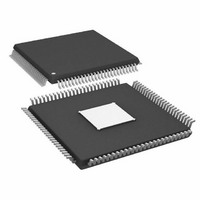
IC MUX/DEMUX QUAD BUFF 100TQFP
Manufacturer
Analog Devices Inc
Series
XStream™r
Datasheet
1.AD8159ASVZ.pdf
(24 pages)
Specifications of AD8159ASVZ
Applications
2:1 Multiplexer/1:2 De-Multiplexer
Interface
Serial
Voltage - Supply
3 V ~ 3.6 V
Package / Case
100-TQFP Exposed Pad, 100-eTQFP, 100-HTQFP, 100-VQFP
Mounting Type
Surface Mount
Crosspoint Switch Type
Digital
Input / Output Configuration
LVPECL, CML / CML
Control Interface
Parallel
Supply Voltage Range
3V To 3.6V
Operating Temperature Range
-40°C To +85°C
Lead Free Status / RoHS Status
Lead free / RoHS Compliant
Available stocks
Company
Part Number
Manufacturer
Quantity
Price
Company:

Part Number:
AD8159ASVZ
Manufacturer:
Analog Devices Inc
Quantity:
135
Company:
Part Number:
AD8159ASVZ
Manufacturer:
AnalogDevices
Quantity:
321
Company:
Part Number:
AD8159ASVZ
Manufacturer:
ADI
Quantity:
174
Company:
Part Number:
AD8159ASVZ
Manufacturer:
Analog Devices Inc
Quantity:
10 000
Part Number:
AD8159ASVZ
Manufacturer:
ADI/亚德诺
Quantity:
20 000


INTERFACING TO THE AD8159
TERMINATION STRUCTURES
To determine the best strategy for connecting to the high speed
pins of the AD8159, the user must first be familiar with the on-chip
termination structures. The AD8159 contains multiple types of
these structures (see Figure 39, Figure 40, and Figure 41). Note
that Port C has a slightly modified termination structure to support
the bidirectional feature.
For input and bidirectional ports, the termination structure
consists of two 55 Ω resistors connected to a termination supply
and an 1173 Ω resistor connected across the differential inputs,
the latter being a result of the finite differential input impedance
of the equalizer.
For output ports, there are two 50 Ω resistors connected to the
termination supply. Note that the differential input resistance
for both structures is the same, 100 Ω.
IP_xx
IN_xx
V
V
V
TTI
CC
EE
Figure 40. Simplified Output Circuit (Port A or Port B)
V
V
V
V
IP
IN
IP
IN
Figure 41. Simplified Output Circuit (Port C)
50Ω
55Ω
Figure 39. Simplified Input Circuit
1173Ω
1173Ω
I
I
T
T
55Ω
50Ω
55Ω
55Ω
V
V
OP_xx
ON_xx
V
V
V
OP_xx
ON_xx
V
CC
TTO
EE
CC
TTOI
EE
Rev. B | Page 19 of 24
INPUT COMPLIANCE
The range of allowable input voltages is determined by the
fundamental limitations of the active input circuitry. This range
of signals is normally a function of the common-mode level of
the input signal, the signal swing, and the supply voltage. For a
given input signal swing, there is a range of common-mode
voltages that keeps the high and low voltage excursions within
acceptable limits. Similarly, for a given common-mode input
voltage, there is a maximum acceptable input signal swing.
There is also a minimum signal swing that the active input
circuitry can resolve reliably.
Figure 22 and Figure 25 summarize the input voltage ranges for
all ports. Note that the input range is different when comparing
bidirectional ports to strictly input ports. This is a consequence
of the additional circuitry required to support the bidirectional
feature on Port C.
AC Coupling
One way to simplify the input circuit and make it compatible
with a wide variety of driving devices is to use ac coupling. This
has the effect of isolating the dc common-mode levels of the driver
and the AD8159 input circuitry. AC coupling requires a capacitor
in series with each single-ended input signal, as shown in Figure 42.
This should be done in a manner that does not interfere with
the high speed signal integrity of the PCB.
When ac coupling is used, the common-mode level at the input
of the device is equal to V
swings above and below V
Figure 22 and Figure 25 to determine the acceptable range of
common-mode levels and signal swing levels that satisfy the
input range of the AD8159.
If dc coupling is required, determining the input common-mode
level is less straightforward because the configuration of the
driver must also be considered. In most cases, the user sets V
on the AD8159 to the same level as the driver output termination
voltage, V
flowing between the two supplies. As a practical matter, both
devices can be terminated to the same physical supply.
50Ω
V
TTOD
TTOD
Figure 42. AC Coupling Input Signal of the AD8159
DRIVER
. This prevents a continuous dc current from
50Ω
C
C
P
N
TTI
TTI
IP_xx
IN_xx
. The single-ended input signal
equally. The user can then use
AD8159
1173Ω
V
55Ω
TTI
/V
TTIO
55Ω
AD8159
V
V
CC
EE
TTI
Related parts for AD8159ASVZ
Image
Part Number
Description
Manufacturer
Datasheet
Request
R

Part Number:
Description:
SENSOR GAS FOR CO/NO2 EXHAUST
Manufacturer:
GE Sensing
Datasheet:

Part Number:
Description:
±1.7g Dual-Axis IMEMS Accelerometer Evaluation Board
Manufacturer:
Analog Devices Inc
Datasheet:

Part Number:
Description:
Inertial Sensor Evaluation System
Manufacturer:
Analog Devices Inc
Datasheet:
Part Number:
Description:
Manufacturer:
Analog Devices Inc
Datasheet:
Part Number:
Description:
Manufacturer:
Analog Devices Inc
Datasheet:
Part Number:
Description:
Manufacturer:
Analog Devices Inc
Datasheet:
Part Number:
Description:
Manufacturer:
Analog Devices Inc
Datasheet:
Part Number:
Description:
Manufacturer:
Analog Devices Inc
Datasheet:
Part Number:
Description:
Manufacturer:
Analog Devices Inc
Datasheet:
Part Number:
Description:
Manufacturer:
Analog Devices Inc
Datasheet:
Part Number:
Description:
Manufacturer:
Analog Devices Inc
Datasheet:
Part Number:
Description:
Manufacturer:
Analog Devices Inc
Datasheet:
Part Number:
Description:
Manufacturer:
Analog Devices Inc
Datasheet: