532903-4 TE Connectivity, 532903-4 Datasheet

High Speed / Modular Connectors HDI RECEP ASSY 4 ROW 280

532903-4

Manufacturer Part Number
532903-4
Description
High Speed / Modular Connectors HDI RECEP ASSY 4 ROW 280
Manufacturer
TE Connectivity
Series
AMP-HDI Seriesr
Datasheets

Specifications of 532903-4

Product Type
Receptacles
Number Of Rows
4
Number Of Positions / Contacts
40
Pitch
2.54 mm
Mounting Style
Through Hole
Termination Style
Solder
Contact Plating
Gold
Gender
Receptacle
Pcb Mount Style
Through Hole
Pcb Mounting Orientation
Right Angle
Make First / Break Last
No
Pcb Mount Retention
Without
Termination Post Length (mm [in])
3.05 [0.120]
Solder Tail Contact Plating
Tin
Number Of Positions
140
Centerline (mm [in])
2.54 [0.100]
Contact Configuration
Four-Beam
Contact Plating, Mating Area, Material
Gold (30)
Contact Base Material
Copper Alloy
Underplate Material
Nickel
Mating Alignment
Without
Housing Material
PPS
Housing Color
Brown
Housing Material Temperature
High
Center Guide
Without
Government/industry Qualification
No
Rohs/elv Compliance
ELV compliant, 5 of 6 Compliant
Lead Free Solder Processes
Not suitable for lead free processing
Lead Free Status / Rohs Status
 Details
1.
1.1.
1.2.
2.
2.1.
2.2.
3.
3.1.
3.2.
3.3.
©2011 Tyco Electronics Corporation,
a TE Connectivity Ltd. Company
All Rights Reserved
TE logo is a trademark.
SCOPE
Content
This specification covers perform ance, tests and quality requirem ents for TE Connectivity (TE) high
density interconnect connector. These are box type receptacle and pin 2 piece connectors which
provide a connection m ethod on .100 inch centerline. Connectors are available in 2, 3 and 4 row
configuration.
Qualification
W hen tests are perform ed on subject product line, procedures specified in 109 Series Test
Specifications shall be used unless otherwise specified. All inspections shall be perform ed using
applicable inspection plan and product drawing.
APPLICABLE DOCUM ENTS
The following docum ents form a part of this specification to the extent specified herein. Unless
otherwise specified, latest edition of the docum ent applies. In the event of conflict between
requirem ents of this specification and product drawing, product drawing shall take precedence. In the
event of conflict between requirem ents of this specification and referenced docum ents, this
specification shall take precedence.
TE Docum ents
!
!
!
Military Standard
MIL-STD-275: Printed W iring for Electronic Equipm ent
REQUIREMENTS
Design and Construction
Connectors shall be of design, construction and physical dim ensions specified on applicable product
drawing.
Materials
!
!
Ratings
!
!
109-1: General Requirem ents for Test Specifications
109 Series: Test Specifications as indicated in Figure 1
501-48: Qualification Test Report
Term inal:
Housing: Therm oplastic, glass filled, UL 94V-0
Current: 3 am peres m axim um per contact, 2.25 am peres continuous per contact at room am bient,
with not m ore than 2 adjacent or opposing circuits carrying this current.
Operating Tem perature: -65 to 125°C for gold contacts
Receptacle: Beryllium copper or copper nickel silicon
Pin: Phosphor bronze or brass
| Indicates change
*Trademark
Product
Specification
Connector, Interconnect, High Density
For latest revision, visit our website at www.te.com/documents.
For Regional Customer Service, visit our website at www.te.com
Other products, logos, and company names might be trademarks of their respective owners.
108-9063
11Mar11 Rev C
1 of 6
LOC B

Related parts for 532903-4

532903-4 Summary of contents

Page 1

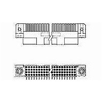
... SCOPE 1.1. Content This specification covers perform ance, tests and quality requirem ents for TE Connectivity (TE) high density interconnect connector. These are box type receptacle and pin 2 piece connectors which provide a connection m ethod on .100 inch centerline. Connectors are available and 4 row configuration. ...

Page 2

Perform ance and Test Description Connectors shall be designed to m eet electrical, m echanical and environm ental perform ance requirem ents specified in Figure 1. 3.5. Test Requirem ents and Procedures Sum m ary Test Description Exam ination ...

Page 3

Test Description Unm ating force. Contact retention. Contact engaging force. Contact separating force. Durability. Resistance to soldering heat. Insertion force, ACTION PIN. Retention force, ACTION PIN. Torque, ACTION PIN. Therm al shock. Hum idity-tem perature cycling. Rev C Requirem ent ...

Page 4

Connector Tests and Sequences Test or Exam ination Exam ination of product Term ination resistance, specified current Term ination resistance, low level Dielectric withstanding voltage Insulation resistance Vibration Physical shock Mating force Unm ating force Contact retention Contact engaging ...

Page 5

QUALITY ASSURANCE PROVISIONS 4.1. Qualification Testing A. Sam ple Selection Connector housings and contacts shall be prepared in accordance with applicable Instruction Sheets and shall be selected at random from current production. Test groups 1, 2 and 3 shall ...

Page 6

Term ination Resistance Measurem ent Points Note: (1) Tolerance: ±.005 as applicable, unless otherwise specified. (2) Material: Tool steel (3) Heat Treat: Rockwell C 50-55 (4) Gage Surface: Shall be clean of contam inants or lubricants Rev C Figure 3 ...

Related keywords