532903-4 TE Connectivity, 532903-4 Datasheet - Page 3
532903-4
Manufacturer Part Number
532903-4
Description
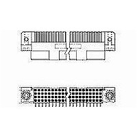
High Speed / Modular Connectors HDI RECEP ASSY 4 ROW 280
Manufacturer
TE Connectivity
Series
AMP-HDI Seriesr
Specifications of 532903-4
Product Type
Receptacles
Number Of Rows
4
Number Of Positions / Contacts
40
Pitch
2.54 mm
Mounting Style
Through Hole
Termination Style
Solder
Contact Plating
Gold
Gender
Receptacle
Pcb Mount Style
Through Hole
Pcb Mounting Orientation
Right Angle
Make First / Break Last
No
Pcb Mount Retention
Without
Termination Post Length (mm [in])
3.05 [0.120]
Solder Tail Contact Plating
Tin
Number Of Positions
140
Centerline (mm [in])
2.54 [0.100]
Contact Configuration
Four-Beam
Contact Plating, Mating Area, Material
Gold (30)
Contact Base Material
Copper Alloy
Underplate Material
Nickel
Mating Alignment
Without
Housing Material
PPS
Housing Color
Brown
Housing Material Temperature
High
Center Guide
Without
Government/industry Qualification
No
Rohs/elv Compliance
ELV compliant, 5 of 6 Compliant
Lead Free Solder Processes
Not suitable for lead free processing
Lead Free Status / Rohs Status
Details


Unm ating force.
Contact retention.
Contact engaging force.
Contact separating force.
Durability.
Resistance to soldering heat.
Insertion force, ACTION PIN.
Retention force, ACTION PIN.
Torque, ACTION PIN.
Therm al shock.
Hum idity-tem perature cycling.
Rev C
Test Description
No physical dam age.
40 pounds m axim um per pin.
Pin shall not dislodge from printed
.4 ounces m inim um average per
contact.
Contacts shall not dislodge from its
norm al locking position.
4 ounces m axim um per contact.
.1 ounce m inim um .
No physical dam age.
.020 ohm s m axim um term ination
resistance, low level.
Contact separation force.
wiring board.
Pin shall not m ove or dislodge from
printed wiring board.
.020 ohm s m axim um term ination
resistance, low level.
1000 m egohm s final insulation
resistance.
ENVIRONMENTAL
Figure 1 (end)
Requirem ent
Measure force to engage using
Size 3 tim es using gage 2, insert
Subject term inal posts m ounted on
Fully insert pin into printed wiring
Measure force necessary to unm ate
connector assem bly.
Calculate force per contact.
TE Spec 109-42, Condition A.
Apply axial load of 3 pounds to
individual contacts.
TE Spec 109-30.
gage 2.
See Figure 4.
TE Spec 109-35.
gage 1 and m easure force to
separate.
See Figure 4.
TE Spec 109-35.
Mate and unm ate pin and
receptacle connectors for 250
cycles.
TE Spec 109-27.
printed circuit boards to solder bath
at 260 ±5 C for 10 ±2 seconds.
Spec 109-63-3.
board hole.
Apply an axial load of 10 pounds for
10 seconds.
Apply 2 inch ounces for 10 seconds
in both directions.
Subject m ated connectors to 5
cycles between -65 and 125°C.
TE Spec 109-22.
Subject m ated connectors to 10
hum idity-tem perature cycles
between 25 and 65°C at 95% RH.
TE Spec 109-23, Method III,
Condition B, less steps 7 a and 7b.
Procedure
108-9063
3 of 6
Related parts for 532903-4
Image
Part Number
Description
Manufacturer
Datasheet
Request
R

Part Number:
Description:
High Speed / Modular Connectors RECPT R/A 100POS AU
Manufacturer:
TE Connectivity
Datasheet:
Part Number:
Description:
High Speed / Modular Connectors HDI RECPT 4RW 300P 224
Manufacturer:
TE Connectivity
Datasheet:
Part Number:
Description:
High Speed / Modular Connectors HDI RECP ASSY 4 ROW 28
Manufacturer:
TE Connectivity
Datasheet:
Part Number:
Description:
High Speed / Modular Connectors HDI RECP ASSY 4 ROW 180 POS
Manufacturer:
TE Connectivity
Datasheet:
Part Number:
Description:
HDI RECP ASSY 4 ROW 220 POS
Manufacturer:
TE Connectivity
Datasheet:
Part Number:
Description:
HDI RECP ASSY 4 ROW 128 POS
Manufacturer:
TE Connectivity
Datasheet:
Part Number:
Description:
High Speed / Modular Connectors HDI RECP 4RW 200P
Manufacturer:
TE Connectivity

Part Number:
Description:
Printers THERMAL PRINTER HS-SLEEVE MARKER
Manufacturer:
TE Connectivity


Part Number:
Description:
Manufacturer:
TE Connectivity
Datasheet:


Part Number:
Description:
Manufacturer:
TE Connectivity
Datasheet:

Part Number:
Description:
Manufacturer:
TE Connectivity
Datasheet: