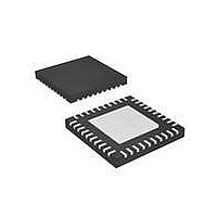
MAX14502AETL+ Maxim Integrated Products, MAX14502AETL+ Datasheet - Page 30

MAX14502AETL+
Manufacturer Part Number
MAX14502AETL+
Description
IC CARD READER USB-SD 40-TQFN
Manufacturer
Maxim Integrated Products
Type
Smart Card Interface ICr
Datasheet
1.MAX14502AETL.pdf
(41 pages)
Specifications of MAX14502AETL+
Applications
USB
Interface
I²C
Voltage - Supply
1.8 V ~ 3.3 V
Package / Case
40-TQFN Exposed Pad
Mounting Type
Surface Mount
Maximum Operating Temperature
+ 85 C
Minimum Operating Temperature
- 40 C
Mounting Style
SMD/SMT
Lead Free Status / RoHS Status
Lead free / RoHS Compliant
Hi-Speed USB-to-SD Card
Readers with Bypass
Figure 19. Format for Reading
Figure 20. Format for Reading Multiple Registers
• 56-bump WLP version, containing one port and two
The SD card clock frequency is the lower of the maxi-
mum the card can support as read from the SD card
and base SD clock (base SD clock is determined from
values shown in Table 5). The MAX14500–MAX14503
30
SD cards. The host SD ports 1 and 2 are connected
together at the host. This configuration allows two
SD cards connected to one host, but only one SD
card is connected to the host at a time. The host
uses the MAX14500–MAX14503’s internal SD port
switches to multiplex between the cards. This con-
figuration can also be used to limit the bus capaci-
tive loading of having two cards connected at the
same time to the bus (Figure 4).
______________________________________________________________________________________
S
S
S
S
D7
D7
1
1
1
1
D6
D6
1
1
1
1
SD Card Clock Frequency
REGISTER 0x01 READ DATA
D5
REGISTER 0x03 READ DATA
D5
1
1
1
1
ADDRESS = 0xE0
ADDRESS = 0xE1
ADDRESS = 0xE0
ADDRESS = 0xE1
D4
D4
0
1
0
0
D3
D3
0
0
0
0
D2
D2
0
0
0
0
D1
D1
0
0
0
0
0 = WRITE
0 = WRITE
1 = READ
1 = READ
D0
D0
0
1
0
1
A
A
A
A
A
A
P
D7
D7
D7
0
internally read the max frequency directly from the SD
card. In I
programmable to values lower than the maximum
allowed by the SD card, helping with issues such as
excessive bus capacitance causing data errors.
Table 5. Maximum SD Card Clock Frequency
0
INPUT FREQUENCY (MHz)
D6
D6
D6
0
0
REGISTER 0x00 READ DATA
D5
REGISTER 0x02 READ DATA
D5
REGISTER ADDRESS = 0x00
REGISTER ADDRESS = 0x01
REGISTER 0x01 READ DATA
D5
0
0
2
C control, the maximum clock frequency is
D4
D4
D4
0
19.2
0
12
13
26
D3
D3
D3
0
0
D2
D2
D2
0
0
D1
D1
D1
0
0
D0
D0
D0
0
1
BASE SD CLOCK (MHz)
A/A
A
A
A
A
P
P
P
48
52
48
52


