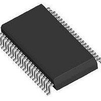
LV8731V-TLM-H ON Semiconductor, LV8731V-TLM-H Datasheet - Page 4

LV8731V-TLM-H
Manufacturer Part Number
LV8731V-TLM-H
Description
Motor / Motion / Ignition Controllers & Drivers 9-32VSteppingMotor 2chBrush Motor Dr
Manufacturer
ON Semiconductor
Type
Stepper Motor Driverr
Datasheet
1.LV8731V-TLM-H.pdf
(26 pages)
Specifications of LV8731V-TLM-H
Product
Stepper Motor Controllers / Drivers
Operating Supply Voltage
9 V to 32 V
Supply Current
3.2 mA
Mounting Style
SMD/SMT
Package / Case
SSOP-44
Operating Temperature
- 20 C to + 85 C
Supply Voltage (min)
9 V
Motor Type
Stepper
No. Of Outputs
2
Output Current
2A
Supply Voltage Range
9V To 32V
Driver Case Style
SSOP
No. Of Pins
44
Operating Temperature Range
-20°C To +85°C
Svhc
No SVHC (20-Jun-2011)
Rohs Compliant
Yes
Lead Free Status / Rohs Status
Details
Available stocks
Company
Part Number
Manufacturer
Quantity
Price
Company:
Part Number:
LV8731V-TLM-H
Manufacturer:
ON Semiconductor
Quantity:
8
Part Number:
LV8731V-TLM-H
Manufacturer:
ON/安森美
Quantity:
20 000
Substrate Specifications (Substrate recommended for operation of LV8731V)
Cautions
Size
Material
Copper wiring density : L1 = 85% / L2 = 90%
1) The data for the case with the Exposed Die-Pad substrate mounted shows the values when 90% or more of the
2) For the set design, employ the derating design with sufficient margin.
3) After the set design, be sure to verify the design with the actual product.
(1)Maximum value 80% or less for the voltage rating
(2)Maximum value 80% or less for the current rating
(3)Maximum value 80% or less for the temperature rating
Exposed Die-Pad is wet.
Stresses to be derated include the voltage, current, junction temperature, power loss, and mechanical stresses such as
vibration, impact, and tension.
Accordingly, the design must ensure these stresses to be as low or small as possible.
The guideline for ordinary derating is shown below :
Confirm the solder joint state and verify also the reliability of solder joint for the Exposed Die-Pad, etc.
Any void or deterioration, if observed in the solder joint of these parts, causes deteriorated thermal conduction,
possibly resulting in thermal destruction of IC.
L1 : Copper wiring pattern diagram
: Glass epoxy
: 90mm × 90mm × 1.6mm (two-layer substrate [2S0P])
3.25
2.20
4.0
3.0
2.0
1.0
– 20
0
Two-layer circuit board 1 *1
Two-layer circuit board 2 *2
*1 With components mounted on the exposed die-pad board
*2 With no components mounted on the exposed die-pad board
0
Ambient temperature, Ta – °C
LV8731V
20
Pd max – Ta
40
60
L2 : Copper wiring pattern diagram
80
1.69
1.14
100
No.A1482-4/26


