T3DDT0 GIC, T3DDT0 Datasheet - Page 41
T3DDT0
Manufacturer Part Number
T3DDT0
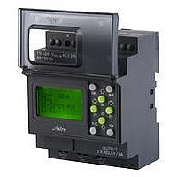
Description
TIME SWITCH, ASTRO, 3-PHASE CONTROL
Manufacturer
GIC
Datasheet
1.T3DDT0.pdf
(67 pages)
Specifications of T3DDT0
Contact Style
SPST
Contact Current Max
8A
Controller Output
Digital
Rohs Compliant
Yes


Programmable Logic Controller
• Supports upto 48 I/Os
• 250 lines of ladder programming
• 16 soft text messages,
40
Cat. No.
Parameters
Supply Voltage
Supply Variation
Max. Supply current
Power Consumption
Analog input range
Digital input range
Digital inputs
Analog inputs
Modbus Communication
Switching contacts
Timers
Counters
Analog Functions
Time Switches
Compare Counters
Soft Messages
Auxiliary Relays
I/O Extension (Max)
Power reserve (for clock only)
Lines for ladder program
Protection
External Protection
Storage temperature
Operating temperature
Maximum Relative Humidity
Mounting
Dimensions (W x H x D)
EMI/ EMC
Radio Interference Suppression
ESD
Electrical Fast Transients
Surges
Voltage Dips
Mechanical Resistance :
Immunity to Vibrations
Certification
Weight
MOUNTING DIMENSION (mm)
(32 digital inputs & 16 digital outputs)
Time Switches, Compare Counters
72.0
G7DDT9
110-240 VAC, 50-60Hz
-20% to +10% of normal voltage
36 mA
~5W
N A
(0-40 VAC) OFF, (70-265 VAC) ON
8
N A
Yes (RTU) (Slave)
4 SPST Relays, 8A @ 240 VAC / 5A @ 30 VDC (resistive)
16
16 (up / down &retentive selectable)
N A
16 (weekly / daily)
16
16 Priority Driven
32
Yes (3)
150h (lithium Battery) at 0
250
IP20 for front panel only (Conforming to IEC 60529)
Fuse 250 mA
-20° C to +70°C
35 to 85 % no condensation
Base / DIN rail
72 X 65 X 90 (in mm)
CISPR 14-1 Class B
IEC 61000-4-2 Level III
IEC 61000-4-4 Level IV
IEC 61000-4-5 Level III
IEC 61000-4-11
Vibration Tests as per IEC 68-2-6
248 g (unpacked)
0° C to +55°C
17.0
RoHS
65.0
Compliant
LISTED
• Backlit LCD Screen for display & modification of
• PC software for programming, online & offline
• Designed for use in automation for commercial &
pre-selected parameters of functional blocks,
viewing I/O status and programming on the device
simulation, documentation & printing
Industrial sectors
o
C
to +55 C
o
MEMORY
GFDNN3
CARD
TM
SUPPLY
EXT
INTERFACE
SERIAL
GFDNN2
FUSE 1
CABLE
110 ~ 240 V AC
L N
PROGRAM
RUN
PARAMETERS
UTILITIES
Q1
CONNECTION DIAGRAM
I1
I2
Q2
I3
INPUTS
OUTPUTS
I4
G8DDT9
12-24 VDC
360 mA
0 to 10 VDC
(0-4 VDC) OFF, (7-26.4 VDC) ON
6
2 (can be used digitally)
12
Fuse 500 mA
232 g (unpacked)
I5
Q3
I6
INPUT
8 X AC
I7 I8
4 x RELAY / 8A
OUTPUT
DEL
ESC
Z1
Q4
Z4
Z2
C1 C2
ALT
Z3
OK
110 ~ 240 V AC
L N
1
1
OP1
2
2
OP
1
3
3
4
IP
4
2
ADDITIONAL
5
OP2
3
ADDITIONAL
INPUTS
OUTPUTS
6
SEL
INPUT
4
7
5
8
OP3
6
A
B
C
INPUT
8 X AC
7
Extension Module
4 x RELAY / 8A
OUTPUT
8
OP4
C1 C2
UP TO
3 EXTENSION MODULES
Related parts for T3DDT0
Image
Part Number
Description
Manufacturer
Datasheet
Request
R

Part Number:
Description:
TERM BLOCK HEADER 6POS 7.62MM
Manufacturer:
Phoenix Contact
Datasheet:

Part Number:
Description:
TERM BLOCK PLUG 5POS 7.62MM
Manufacturer:
Phoenix Contact
Datasheet:
Part Number:
Description:
TERM BLOCK PLUG 6POS 7.62MM
Manufacturer:
Phoenix Contact
Datasheet:
Part Number:
Description:
TERM BLOCK PLUG 5POS 7.62MM
Manufacturer:
Phoenix Contact
Datasheet:
Part Number:
Description:
TERM BLOCK HEADER 6POS 7.62MM
Manufacturer:
Phoenix Contact
Datasheet:
Part Number:
Description:
TERM BLOCK PLUG 6POS 7.62MM
Manufacturer:
Phoenix Contact
Datasheet:
Part Number:
Description:
TERM BLOCK PLUG 11POS 7.62MM
Manufacturer:
Phoenix Contact
Datasheet:

Part Number:
Description:
TERM BLOCK PLUG 12POS 7.62MM
Manufacturer:
Phoenix Contact
Datasheet:

Part Number:
Description:
GIC 2.0 REC CONT TIN PLATE TYPE
Manufacturer:
TE Connectivity
Datasheet: