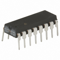
HI1-0539-5 Intersil, HI1-0539-5 Datasheet

HI1-0539-5
Specifications of HI1-0539-5
Available stocks
Related parts for HI1-0539-5
HI1-0539-5 Summary of contents
Page 1
... This problem is minimized in the HI-539 by symmetrical placement of critical circuitry with respect to the few heat producing devices. Supply voltages are ±15V and power consumption is only 2.5mW. Ordering Information TEMP. o PART NUMBER RANGE ( C) PACKAGE HI1-0539 CERDIP Pinouts HI-539 (CERDIP) TOP VIEW ...
Page 2
Absolute Maximum Ratings ...
Page 3
Electrical Specifications Supplies = Unless Otherwise Specified (Continued) PARAMETER On Resistance ∆r (Side A-Side B) ON, Off Input Leakage Current, I S(OFF) ∆I (Side A-Side B) S(OFF), Off Output Leakage Current, I D(OFF) ∆I (Side A-Side B) D(OFF), ...
Page 4
Electrical Specifications Supplies = Unless Otherwise Specified (Continued) PARAMETER Current, l- Supply Voltage Range NOTES: 2. See Figures 2B, 2C, 2D. The condition ±10V means: l and I : S(OFF) D(OFF +10V -10V), then S D ...
Page 5
Test Circuits and Waveforms 10 I D(ON D(OFF) S(OFF TEMPERATURE ( FIGURE 2A. LEAKAGE CURRENT vs TEMPERATURE HI-539 I A S(OFF) ±10V ± 10V A 0 † Similar Connection For Side “B” FIGURE ...
Page 6
Test Circuits and Waveforms 320 300 280 260 240 220 200 LOGIC LEVEL (HIGH) (V) FIGURE 4A. ACCESS TIME vs LOGIC LEVEL (HIGH 50% +10V 10 ...
Page 7
Test Circuits and Waveforms 50% ENABLE DRIVE (V 50% 90% t ON(EN) t OFF(EN) FIGURE 6A. MEASUREMENT POINTS 7 HI-539 o Unless Otherwise Specified +15V -15V ...
Page 8
Test Circuits and Waveforms HI-539 1kHz, 15V P-P 350Ω † AD606 or BB3630, for Example FIGURE 7A. SINGLE-ENDED CROSSTALK TEST CIRCUIT Application Information General The Hl-539 accepts inputs in the range -15V to +15V, with performance guaranteed over the ±10V ...
Page 9
EQUIVALENT WIDTH OF P.C. CONDUCTOR WIRE GAGE (2 oz. Cu) 18 0.47” 20 0.30” 22 0.19” 24 0.12” 26 0.075” 28 0.047” 30 0.029” 32 0.018” Provide Path For I BIAS The input bias current for any DC-coupled amplifier must ...
Page 10
SOURCE POWER SUPPLY COMMON NOTE: The amplifier in Figure 8A is unusable because its bias currents cannot return to the power supply. Figure 8B shows two alternative paths for these bias currents: either a pair of resistors, or (better) ...
Page 11
Die Characteristics DIE DIMENSIONS: 92 mils x 100 mils METALLIZATION: Type: AlCu ±2k Å Å Thickness: 16k SUBSTRATE POTENTIAL (NOTE): -V SUPPLY NOTE: The substrate appears resistive to the -V conductor at -V potential. SUPPLY Metallization Mask Layout V- IN1A ...
Page 12
... Accordingly, the reader is cautioned to verify that data sheets are current before placing orders. Information furnished by Intersil is believed to be accurate and reliable. However, no responsibility is assumed by Intersil or its subsidiaries for its use; nor for any infringements of patents or other rights of third parties which may result from its use ...


