HW1M-LF2020-20 IDEC, HW1M-LF2020-20 Datasheet - Page 44
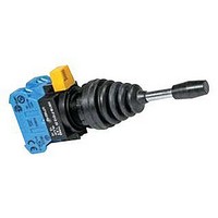
HW1M-LF2020-20
Manufacturer Part Number
HW1M-LF2020-20
Description
84C4816
Manufacturer
IDEC
Datasheet
1.HW1M-LF0101-20.pdf
(51 pages)


• Turn off the power to the HW series control units before
• To avoid a burn on your hand, use the lamp holder tool
Panel Mounting
Remove the contact block from the operator (for transformer
type pilot lights, remove the transformer from the illumina-
tion unit). Remove the locking ring from the operator. Insert
the operator into the panel cut-out from the front, tighten the
locking ring from the back, then install the contact block to
the operator.
• Removing and Installing the Contact Block
1. To remove the operator from the contact block, turn the
2. To reinstall, place the TOP markings on the operator and
• Removing and Installing the Transformer Unit on Pilot
1. Insert a flat screwdriver (5mm wide at the maximum) into
2. To reinstall, place the TOP marking on the illumination
44
ø22
starting installation, removal, wiring, maintenance, and
inspection of the products. Failure to turn power off may
cause electrical shocks or fire hazard.
when replacing lamps.
Lights
Safety Precautions
Instructions
locking lever in the direction of the arrow shown below.
Then the operator can be pulled out.
the contact block mounting adapter in the same direction,
and insert the operator into the contact block mounting
adapter. Then turn the locking lever in the opposite direc-
tion.
the latch hole on the transformer unit as shown in the
photo below, and disengage the latch. Then pull out the
illumination unit.
unit and the latch in the same direction, and push the illu-
mination unit into the transformer unit.
HW
Series
Instructions
• For wiring, use wires of a proper size to meet the voltage
• Notes for Panel Mounting
1. When mounting the operator onto a panel, use the
2. For the contact blocks and transformers housing LED
• Notes for Illuminated Pushbuttons
The full shroud cannot be removed from the extended full
shroud type.
Safety Lever Lock
IDEC strongly recommends using the safety lever lock
(HW9Z-LS, yellow) to prevent heavy vibration or mainte-
nance personnel from unlocking contacts.
1. HW series can be mounted vertically with a minimum
2. Mount the control unit onto the panel, lock the lever, and
3. When the spacing is narrower than the recommended
4. To remove the safety lever lock, insert a flat screwdriver
and current requirements. Tighten the M3.5 terminal
screws to a tightening torque of 1.0 to 1.3
tighten terminal screws may cause overheat and fire.
optional locking ring wrench (MW9Z-T1) to tighten the
locking ring. Tightening torque must not exceed 2.0 N·m.
Do not use pliers. Excessive tightening will damage the
locking ring.
and incandescent lamps, make sure not to press the
lamps too hard, otherwise the lamp socket may be
impaired.
spacing of 50 mm (70 mm for mono-lever switches) but
spacing should be determined to ensure easy operation.
strongly push in the safety lever lock to install.
value, with the lever unlocked, mount the safety lever lock
and insert the contact unit to the operator. Then, lock the
lever and strongly push in the safety lever lock to install.
into the safety lever lock and push upwards.
Screwdriver
Contact Block
Mounting Adapter
Lock Lever
Safety Lever Lock
Safety Lever Lock
Remove
Panel
Operator
N·m
. Failure to
Related parts for HW1M-LF2020-20
Image
Part Number
Description
Manufacturer
Datasheet
Request
R

Part Number:
Description:
Cable; Between IDEC MicroSmart (port 1 or 2) and HG2F/3F/4F; 5 ft.
Manufacturer:
IDEC Corporation
Datasheet:
Part Number:
Description:
Cable; Between IDEC Micro^3C/ONC/MicroSmart (port 2) PLCs and HG2F/3F/4F; 5 ft.
Manufacturer:
IDEC Corporation
Datasheet:
Part Number:
Description:
Angled Key for Idec HS6B Safety Switch
Manufacturer:
IDEC Corporation
Datasheet:
Part Number:
Description:
Accessory, L-Shaped Key for Idec HS5B and HS5E Safety Switch
Manufacturer:
IDEC Corporation
Datasheet:
Part Number:
Description:
Accessory, Straight Key for Idec HS5B and HS5E Safety Switch
Manufacturer:
IDEC Corporation
Datasheet:
Part Number:
Description:
Straight Key for Idec HS6B Safety Switch
Manufacturer:
IDEC Corporation
Datasheet:
Part Number:
Description:
LIGHT TOWER 3 TIER RED/AMBER/GREEN 24VAC/DC WALL MOUNT
Manufacturer:
IDEC Corporation
Datasheet:
Part Number:
Description:
Flat Lens, 24V AC/DC, 1m Cable Length, Alternate: Red Green Color, IP67
Manufacturer:
IDEC Corporation
Datasheet:
Part Number:
Description:
LIGHT TOWER 2 TIER RED/GREEN 24VAC/DC WALL MOUNT
Manufacturer:
IDEC Corporation
Datasheet:
Part Number:
Description:
LIGHT TOWER 2 TIER RED/GREEN 24VAC/DC DIRECT MOUNT
Manufacturer:
IDEC Corporation
Datasheet:

Part Number:
Description:
INDICATOR INCANDESCENT LAMP, GREEN
Manufacturer:
IDEC
Datasheet:

Part Number:
Description:
LAMP, INDICATOR, INCAND, AMB
Manufacturer:
IDEC
Datasheet:
Part Number:
Description:
LAMP, INDICATOR, INCAND, GRN
Manufacturer:
IDEC
Datasheet:
Part Number:
Description:
LAMP, INDICATOR, INCAND, GRN
Manufacturer:
IDEC
Datasheet: