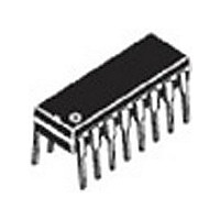
MC10136P ON Semiconductor, MC10136P Datasheet - Page 4

MC10136P
Manufacturer Part Number
MC10136P
Description
Manufacturer
ON Semiconductor
Type
Hexadecimalr
Datasheet
1.MC10136P.pdf
(8 pages)
Specifications of MC10136P
Technology
ECL
Number Of Elements
1
Number Of Bits
4
Logic Family
ECL
Logical Function
Counter
Operating Supply Voltage (typ)
-5.2V
Output Type
Standard
Package Type
PDIP
Propagation Delay Time
11.5ns
Operating Temp Range
-30C to 85C
Operating Supply Voltage (min)
-4.68V
Operating Supply Voltage (max)
-5.72V
Operating Temperature Classification
Commercial
Mounting
Through Hole
Pin Count
16
Lead Free Status / Rohs Status
Not Compliant
Available stocks
Company
Part Number
Manufacturer
Quantity
Price
Company:
Part Number:
MC10136P
Manufacturer:
INDUCTOR
Quantity:
481
Part Number:
MC10136P
Manufacturer:
MOTOROLA/摩托罗拉
Quantity:
20 000
Company:
Part Number:
MC10136PDS
Manufacturer:
MOT
Quantity:
6 218
1. Individually test each input; apply V
2. Measure output after clock pulse
3. Before test set all Q outputs to a logic high.
4. To preserve reliable performance, the MC10136 (plastic packaged device only) is to be operated in ambient temperatures above 70 C only
Each MECL 10,000 series circuit has been designed to meet the dc specifications shown in the test table, after thermal equilibrium has been
established. The circuit is in a test socket or mounted on a printed circuit board and transverse air flow greater than 500 linear fpm is maintained.
Outputs are terminated through a 50-ohm resistor to –2.0 volts. Test procedures are shown for only one gate. The other gates are tested in the
same manner.
ELECTRICAL CHARACTERISTICS
Power Supply Drain Current
Input Current
Output Voltage
Output Voltage
Threshold Voltage
Threshold Voltage
Switching Times
Propagation Delay
Setup Time
Hold Time
Counting Frequency
Rise Time
Fall Time
when 500lfpm blown air or equivalent heat sinking is provided.
Characteristic
Carry In to Carry Out
Carry In Inputs
Carry In Inputs
Select Inputs
Select Inputs
(20 to 80%)
(20 to 80%)
Data Inputs
Data Inputs
(50 Load)
Clock Input
Logic 1
Logic 0
Logic 1
Logic 0
ILmin
f
Symbol
countdown
@ Test Temperature
f
t
t
t
t
t
t
t
t
t
t
t
t
t
t
t
t
t
t
countup
V
13+14+
13+14–
12+13+
12–13+
10–13+
10+13+
13+12+
13+12–
13+10–
13+10+
V
13+4+
13+4–
10–4–
10+4+
9+13+
7+13+
13+9+
13+7+
V
V
t
t
I
(continued)
I
t
OHA
14+
t
14–
inH
OLA
I
inL
4+
4–
OH
OL
E
to pin under test.
5,6,11,12
Under
Under
14
14
14
14
Test
9,10
4
–30 C
+25 C
+85 C
Pin
13
All
14
14
14
14
14
14
14
14
14
14
14
14
14
14
14
14
14
14
8
7
4
4
4
4
4
(3.)
(2.)
(2.)
(2.)
(2.)
appears at clock input (Pin 13).
http://onsemi.com
MC10136
5,6,11,12
V
V
+1.11V
–0.890
–0.810
–0.700
9,10
IHmax
IHmax
TEST VOLTAGE APPLIED TO PINS LISTED BELOW
13
12
12
7
7
7
7
7
7
7
7
7
7
9
7
7
7
7
4
TEST VOLTAGE VALUES (Volts)
Note 1.
+0.31V
–1.890
–1.850
–1.825
V
V
7, 9
7, 9
7, 9
7, 9
7, 9
7, 9
7, 9
7, 9
ILmin
ILmin
13
13
9
9
9
Pulse In
V
V
–1.205
–1.105
–1.035
12, 13
12, 13
10, 13
10, 13
12, 13
12, 13
10, 13
10, 13
IHAmin
IHAmin
9, 13
7, 13
9, 13
7, 13
12
13
13
13
13
10
10
13
13
13
13
13
13
Pulse Out
V
V
–1.500
–1.475
–1.440
ILAmax
ILAmax
12
14
14
14
14
14
14
14
14
14
14
14
14
14
14
14
14
14
14
4
4
4
4
4
4
–3.2 V
–5.2
–5.2
–5.2
V
V
EE
EE
8
8
8
8
8
8
8
8
8
8
8
8
8
8
8
8
8
8
8
8
8
8
8
8
8
8
8
8
8
8
8
8
8
8
+2.0 V
(V
(V
1, 16
1, 16
1, 16
1, 16
1, 16
1, 16
1, 16
1, 16
1, 16
1, 16
1, 16
1, 16
1, 16
1, 16
1, 16
1, 16
1, 16
1, 16
1, 16
1, 16
1, 16
1, 16
1, 16
1, 16
1, 16
1, 16
1, 16
1, 16
1, 16
1, 16
1, 16
1, 16
1, 16
1, 16
Gnd
CC
)
)


