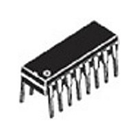
MC10136P ON Semiconductor, MC10136P Datasheet - Page 6

MC10136P
Manufacturer Part Number
MC10136P
Description
Manufacturer
ON Semiconductor
Type
Hexadecimalr
Datasheet
1.MC10136P.pdf
(8 pages)
Specifications of MC10136P
Technology
ECL
Number Of Elements
1
Number Of Bits
4
Logic Family
ECL
Logical Function
Counter
Operating Supply Voltage (typ)
-5.2V
Output Type
Standard
Package Type
PDIP
Propagation Delay Time
11.5ns
Operating Temp Range
-30C to 85C
Operating Supply Voltage (min)
-4.68V
Operating Supply Voltage (max)
-5.72V
Operating Temperature Classification
Commercial
Mounting
Through Hole
Pin Count
16
Lead Free Status / Rohs Status
Not Compliant
Available stocks
Company
Part Number
Manufacturer
Quantity
Price
Company:
Part Number:
MC10136P
Manufacturer:
INDUCTOR
Quantity:
481
Part Number:
MC10136P
Manufacturer:
MOTOROLA/摩托罗拉
Quantity:
20 000
Company:
Part Number:
MC10136PDS
Manufacturer:
MOT
Quantity:
6 218
several MC10136 counters may be cascaded. The Carry In
input overrides the clock when the counter is either in the
increment mode or the decrement mode of operation. This
input allows several devices to be cascaded in a fully
synchronous multistage counter as illustrated in Figure 1.
The carry is advanced between stages as shown with no
external gating. The Carry In of the first device may be left
open. The system clock is common to all devices.
useful for a wide variety of applications. If used with MECL
III devices, prescalers with input toggle frequencies in
excess of 300 MHz are possible. Figure 2 shows such a
prescaler using the MC10136 and MC1670. Use of the
MC10231 in place of the MC1670 permits 200 MHz
operation.
To provide more than four bits of counting capability
The various operational modes of the counter make it
Figure 3. 50 MHz PROGRAMMABLE COUNTER
Figure 1. 12 BIT SYNCHRONOUS COUNTER
NOTE: S1 and S2 are set either for increment or decrement operation.
APPLICATIONS INFORMATION
http://onsemi.com
MC10136
6
counter. The configuration of Figure 3 requires no additional
gates, although maximum frequency is limited to about 50
MHz. The divider modulus is equal to the program input
plus one (M = N + 1), therefore, the counter will divide by
a modulus varying from 1 to 16.
in Figure 4. A pulse swallowing technique is used to speed
the counter operation up to 110 MHz typically. The divider
modulus for this figure is equal to the program input (M =
N). The minimum modulus is 2 because of the pulse
swallowing technique, and the modulus may vary from 2 to
15. This programmable configuration requires an additional
gate, such as
1
/
Figure 4. 100 MHz PROGRAMMABLE COUNTER
2
The MC10136 may also be used as a programmable
A second programmable configuration is also illustrated
MC10131.
Figure 2. 300 MHz PRESCALER
1
/
2
MC10109 and a flip-flop such as


