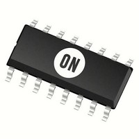
MC74HC595AD ON Semiconductor, MC74HC595AD Datasheet - Page 5

MC74HC595AD
Manufacturer Part Number
MC74HC595AD
Description
Counter Shift Registers 8-Bit 3 State Shift
Manufacturer
ON Semiconductor
Datasheet
1.MC74HC595ADR2G.pdf
(11 pages)
Specifications of MC74HC595AD
Counting Sequence
Serial to Serial/Parallel
Number Of Circuits
2
Package / Case
SOIC-16
Logic Family
74HC
Logic Type
CMOS
Output Type
3-State
Propagation Delay Time
140 ns, 100 ns, 28 ns, 24 ns
Supply Voltage (max)
6 V
Maximum Operating Temperature
+ 125 C
Minimum Operating Temperature
- 55 C
Function
Shift Register
Mounting Style
SMD/SMT
Operating Supply Voltage
2 V to 6 V
Dc
N/A
Lead Free Status / Rohs Status
No RoHS Version Available
Available stocks
Company
Part Number
Manufacturer
Quantity
Price
Company:
Part Number:
MC74HC595AD
Manufacturer:
MOTOROLA
Quantity:
422
Part Number:
MC74HC595AD
Manufacturer:
ON/安森美
Quantity:
20 000
Part Number:
MC74HC595ADR2
Manufacturer:
ON/安森美
Quantity:
20 000
Part Number:
MC74HC595ADR2G
Manufacturer:
ON/安森美
Quantity:
20 000
Company:
Part Number:
MC74HC595ADTG
Manufacturer:
ON
Quantity:
9 400
Company:
Part Number:
MC74HC595ADTR2G
Manufacturer:
TDK
Quantity:
20 000
Part Number:
MC74HC595ADTR2G
Manufacturer:
ON/安森美
Quantity:
20 000
AC ELECTRICAL CHARACTERISTICS
TIMING REQUIREMENTS
Symbol
Symbol
Symbol
t
t
C
C
t
t
TLH
TLH
t
t
THL
THL
C
t
t
r
rec
t
t
t
t
su
su
, t
out
PD
w
w
w
h
in
f
,
,
Power Dissipation Capacitance (Per Package)*
Maximum Output Transition Time, Q
Maximum Output Transition Time, SQ
Maximum Input Capacitance
Maximum Three−State Output Capacitance (Output in
High−Impedance State), Q
Minimum Setup Time, Serial Data Input A to Shift Clock
Minimum Setup Time, Shift Clock to Latch Clock
Minimum Hold Time, Shift Clock to Serial Data Input A
Minimum Recovery Time, Reset Inactive to Shift Clock
Minimum Pulse Width, Reset
Minimum Pulse Width, Shift Clock
Minimum Pulse Width, Latch Clock
Maximum Input Rise and Fall Times
(Figures 3 and 7)
(Figures 1 and 7)
(Figure 5)
(Figure 6)
(Figure 5)
(Figure 2)
(Figure 2)
(Figure 1)
(Figure 6)
(Figure 1)
(Input t
r
A
Parameter
= t
Parameter
Parameter
− Q
f
= 6.0 ns)
H
(C
A
L
H
− Q
= 50 pF, Input t
H
http://onsemi.com
r
= t
5
f
= 6.0 ns)
V
2.0
3.0
4.5
6.0
2.0
3.0
4.5
6.0
2.0
3.0
4.5
6.0
2.0
3.0
4.5
6.0
2.0
3.0
4.5
6.0
2.0
3.0
4.5
6.0
2.0
3.0
4.5
6.0
2.0
3.0
4.5
6.0
V
V
V
CC
2.0
3.0
4.5
6.0
2.0
3.0
4.5
6.0
—
—
V
V
CC
CC
25_C to –55_C
– 55 to 25_C
1000
Typical @ 25°C, V
800
500
400
9.0
5.0
5.0
5.0
5.0
9.0
9.0
9.0
50
40
10
75
60
15
13
50
40
10
60
45
12
10
50
40
10
50
40
10
60
23
12
10
75
27
15
13
10
15
Guaranteed Limit
Guaranteed Limit
v 85_C
v 85_C
300
1000
800
500
400
5.0
5.0
5.0
5.0
75
27
15
13
95
32
19
16
10
15
65
50
13
11
95
70
19
16
65
50
13
11
75
60
15
13
65
50
13
11
65
50
13
11
CC
= 5.0 V
v 125_C
v 125_C
1000
800
500
400
110
110
5.0
5.0
5.0
5.0
90
31
18
15
36
22
19
10
15
75
60
15
13
80
22
19
75
60
15
13
90
70
18
15
75
60
15
13
75
60
15
13
Unit
Unit
Unit
pF
pF
pF
ns
ns
ns
ns
ns
ns
ns
ns
ns
ns


