HR1S-AF5130PB IDEC, HR1S-AF5130PB Datasheet - Page 2
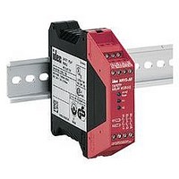
HR1S-AF5130PB
Manufacturer Part Number
HR1S-AF5130PB
Description
47T1436
Manufacturer
IDEC
Datasheet
1.HR1S-AF5130B.pdf
(3 pages)
Specifications of HR1S-AF5130PB
Coil Voltage Vac Nom
24V
Coil Voltage Vdc Nom
24V
Contact Configuration
3NO
Relay Mounting
DIN Rail
External Height
99mm
External Width
22.5mm
External Depth
114mm


Safety Category 3 Example Circuit (using multiple emergency stop switches)
Safety Category 4 Example Circuit (using an emergency stop switch)
HR1S-AF Wiring Diagram
24V AC/DC
24V AC/DC
L (+)
N (–)
L (+)
N (–)
(1) = Start Switch Monitor
F1 (Fuse: 4A gL)
F1 (Fuse: 4A gL)
A1
A2
A1
A2
HR1S-AF
HR1S-AF
Emergency
Stop
Switch
S1
S2
S3
S1
ESC
ESC
S11
S11
ESC: External Start Condition
F1:
K3, 4: Safety contactor
11
12
11
12
11
12
11
12
K3
K4
K3
K4
S33
S33
Protection fuse for the power of
safety relay module
S12
S12
monitoring
monitoring
When
When
Start
Switch
S4
LOGIC
S2
Start
Switch
LOGIC
S34
S21
S34
S21
21
22
21
22
21
22
21
22
S4
S2 13
S22
14
(1)
S22
The Safety Category is achieved by the entire
control system. Take any connected safety
equipment and wiring into consideration.
S39
S39
Emergency
Stop
Switch 1
Emergency
Stop
Switch 2
Emergency
Stop
Switch 3
When not
monitoring
S4
When not
monitoring
S2
K1
K2
K1
K2
K3
K3
13
14
13
14
Safety Output 3 Circuits
K4
K4
23
24
23
24
ESC:
F1:
K3, K4: Safety contactor
33
34
33
34
External Start Condition
Protection fuse for the power of safety relay module
When not using a start switch
(automatic start)
When not monitoring the start switch
start switch cannot be detected)
When monitoring the start switch
(detecting the OFF status of start switch)
Limit switch or interlock switch for guard
opening/closing
A1
A1
A1
A2
S33
S33
S33
S11
S1
Input A
Safety Guard Open
S2
S34 S39
S34 S39
S34 S39
S12
13
14
S2
Start Switch
13
14
Start Switch
S21
13
13
13
S2
Input B
23
23
23
S22
(welding of
33
33
33
Related parts for HR1S-AF5130PB
Image
Part Number
Description
Manufacturer
Datasheet
Request
R

Part Number:
Description:
47T1434
Manufacturer:
IDEC
Datasheet:
Part Number:
Description:
47T1435
Manufacturer:
IDEC
Datasheet:

Part Number:
Description:
93K6228
Manufacturer:
IDEC
Datasheet:

Part Number:
Description:
47T1437
Manufacturer:
IDEC
Datasheet:
Part Number:
Description:
47T1438
Manufacturer:
IDEC
Datasheet:

Part Number:
Description:
47T1439
Manufacturer:
IDEC
Datasheet:
Part Number:
Description:
47T1440
Manufacturer:
IDEC
Datasheet:

Part Number:
Description:
47T1441
Manufacturer:
IDEC
Datasheet:
Part Number:
Description:
47T1442
Manufacturer:
IDEC
Datasheet:

Part Number:
Description:
Cable; Between IDEC MicroSmart (port 1 or 2) and HG2F/3F/4F; 5 ft.
Manufacturer:
IDEC Corporation
Datasheet:
Part Number:
Description:
INDICATOR INCANDESCENT LAMP, GREEN
Manufacturer:
IDEC
Datasheet:

Part Number:
Description:
LAMP, INDICATOR, INCAND, AMB
Manufacturer:
IDEC
Datasheet:
Part Number:
Description:
LAMP, INDICATOR, INCAND, GRN
Manufacturer:
IDEC
Datasheet:
Part Number:
Description:
LAMP, INDICATOR, INCAND, GRN
Manufacturer:
IDEC
Datasheet:
Part Number:
Description:
LAMP, INDICATOR, INCANDESCENT, RED
Manufacturer:
IDEC
Datasheet: